Stackable switch

a technology of electrical switch and assembly, which is applied in the direction of contact mechanism, gaseous heating fuel, stoves or ranges, etc., can solve the problems of large installation space, unduly long actuator and switching mechanism, and large wiring harness, etc., to achieve the effect of minimal spa

Active Publication Date: 2006-12-12
ILLINOIS TOOL WORKS INC
View PDF29 Cites 22 Cited by
  • Summary
  • Abstract
  • Description
  • Claims
  • Application Information

AI Technical Summary

Benefits of technology

[0012]Another advantage of the present invention is providing multiple switches actuated by a single actuator.
[0013]Still another advantage of the present invention is providing multiple switches that require minimal space.
[0014]Still another advantage of the present invention is providing a multi-function switch assembly that can be expanded as required for additional switching functions.
[0015]Other features and advantages of the invention will become apparent to those skilled in the art upon review of the following detailed description, claims and drawings in which like numerals are used to designate like features.

Problems solved by technology

As more and more individual switches for additional functions are combined with a single actuator, the actuator becomes unduly long and the switching mechanisms complex.
However the wiring harness becomes unduly large and complex, and requires significant space for installation.

Method used


Image

  • Stackable switch
  • Stackable switch
  • Stackable switch

Examples


Embodiment Construction

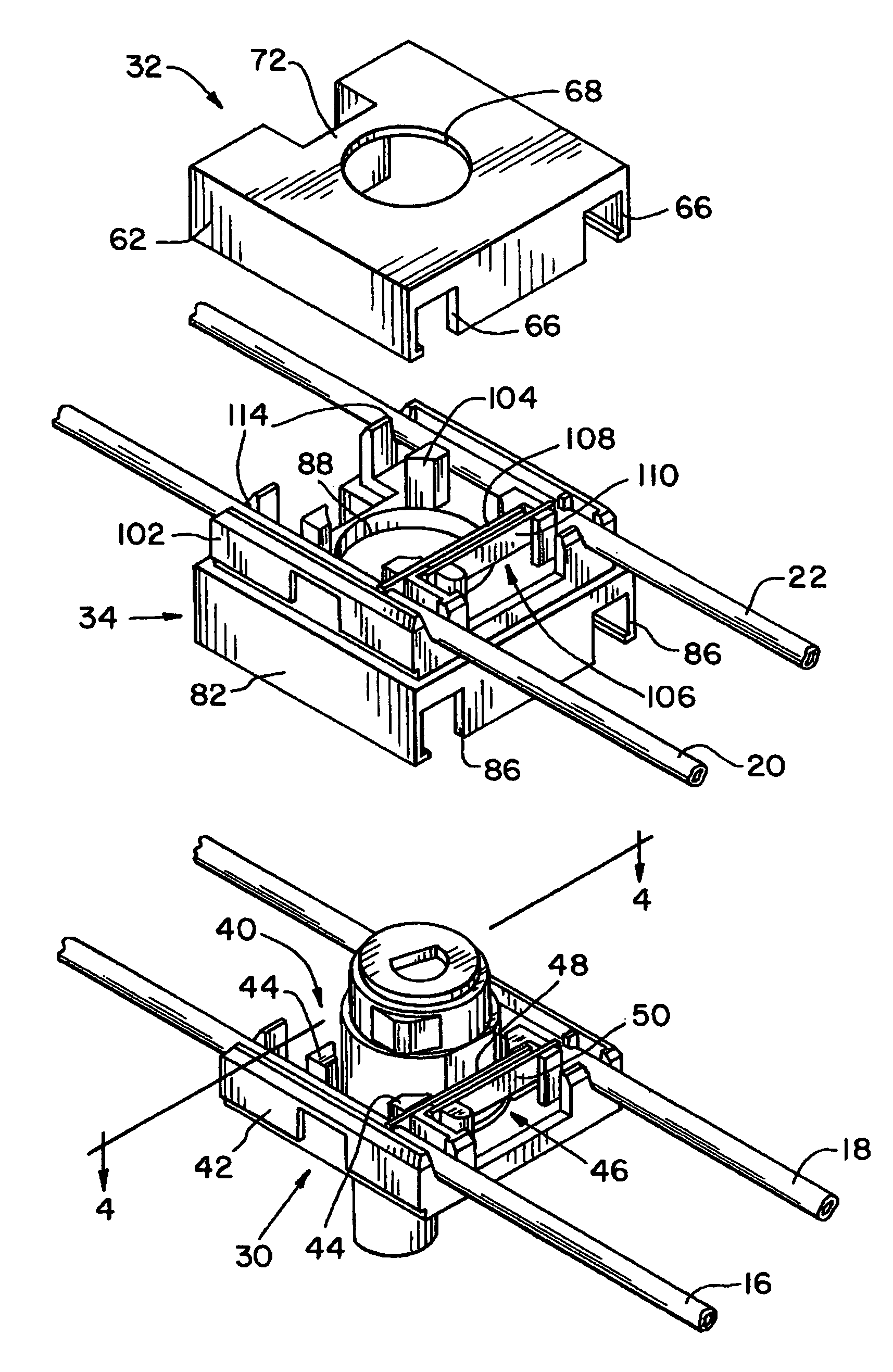
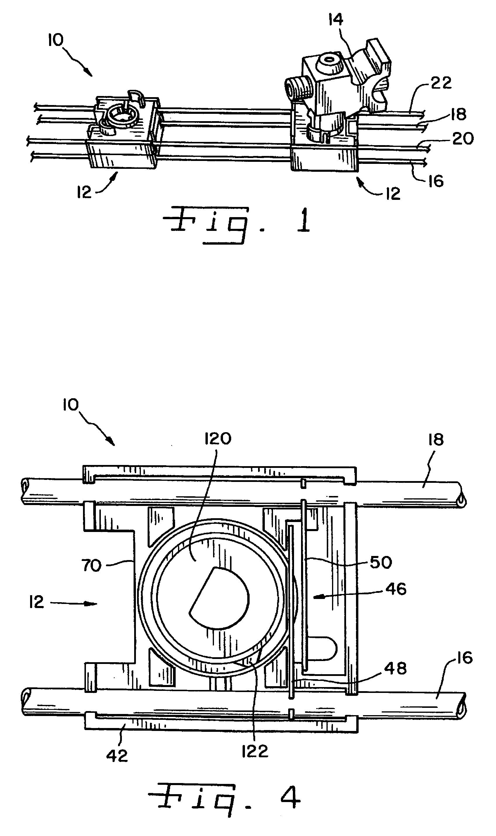
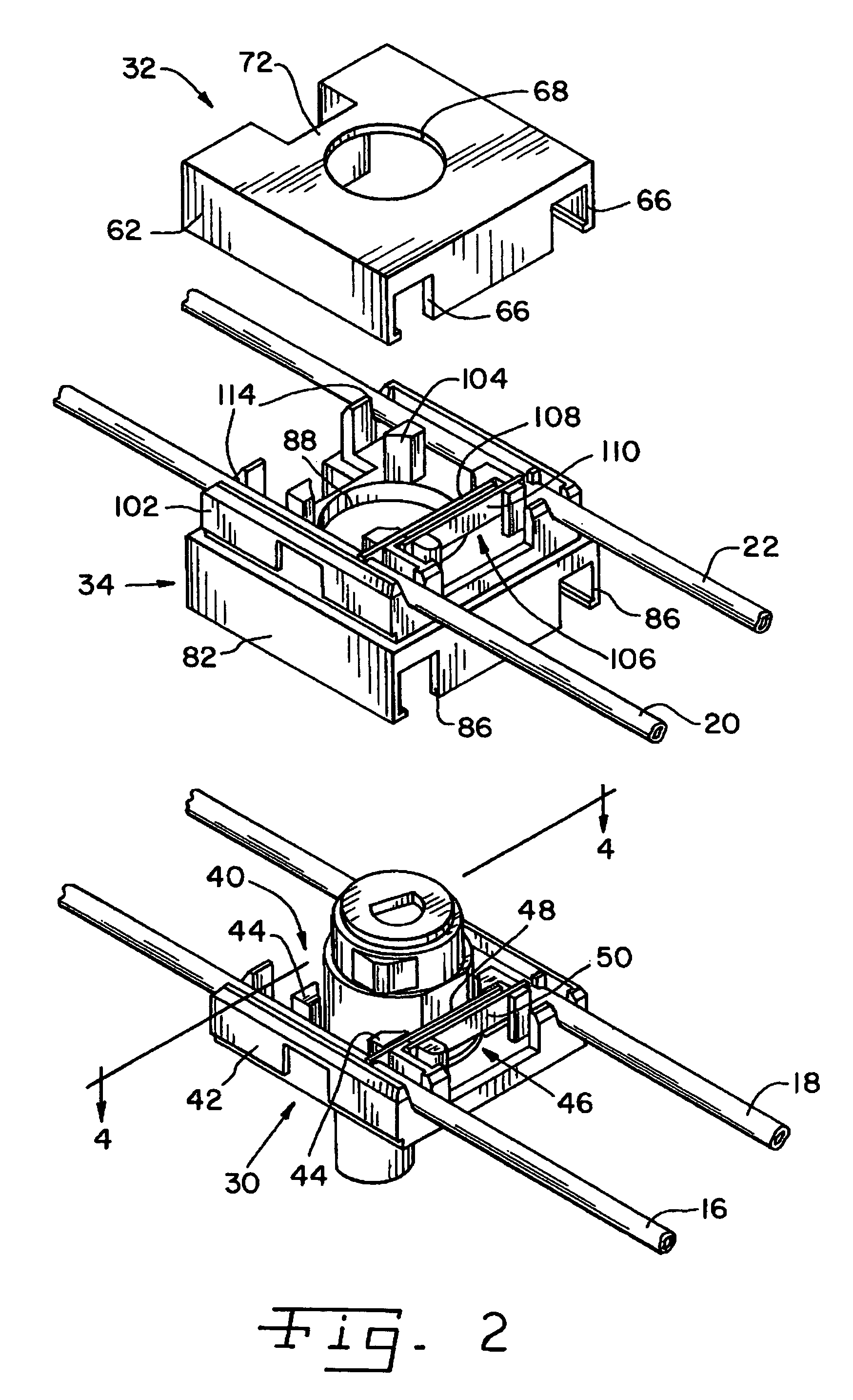
[0021]Referring now more specifically to the drawings and to FIG. 1 in particular, numeral 10 designates a wiring harness having stackable switch assemblies 12 in accordance with the present invention Two switch assemblies 12 are illustrated in FIG. 1 on wiring harness 10; however, as those skilled in the art will understand readily, a single switch assembly 12 may be used where appropriate, and three or more switch assemblies 12 also may be used when required. The present invention works well with a variety of actuators and, as illustrated in FIG. 1, switch assembly 12 works well in an appliance such as a kitchen range having a gas fired burner for which a gas valve 14 is provided. One such gas valve 14 is shown for one switch assembly 12 in FIG. 1. Gas valve 14 is operatively associated with switch assembly 12, as will be described in further detail hereinafter. The other switch assembly 12 can be associated with another gas valve 14 (not shown), or with another form of actuator (...


PUM


Abstract

A stackable switch assembly includes a base switch housing having switch components therein, an intermediate switch housing having second switch components therein, with the intermediate switch housing mechanically engaged with the base switch housing, and a cover mechanically engaged with the intermediate switch housing. Multiple intermediate switch housings can be used between the base switch housing and the cover.

Description

FIELD OF THE INVENTION[0001]The present invention relates generally to electrical switch assemblies that are actuated by rotatable members, and, more particularly, to switches used in wiring harnesses, such as on appliances, including ignition systems for gas-fired appliances.BACKGROUND OF THE INVENTION[0002]Electrical switches having rotatable actuators are used in a variety of applications. For example, it is known to use such switches in gas fueled cooking appliances. An electrical switch assembly is coupled to the rotatable valve stem of the gas valve, to control burner ignition circuitry. When the gas valve stem is rotated to place the valve in the open position and commence gas flow, the burner ignition electrical circuitry is energized to ignite the gas stream at the burner. In this way, stand-by pilot lights are not required, and gas ignition occurs simultaneously with opening the gas valve and commencing the flow of gas. Fuel is not wasted keeping a pilot light burner. Cons...

Claims


Application Information

Patent Timeline
Patent Type & Authority Patents(United States)
IPC IPC(8): H01H1/16
CPCH01H3/0206H01H19/06H01H1/5844H01H19/62F24C3/126
Inventor GJERDE, RICHARD D.
Owner ILLINOIS TOOL WORKS INC
Why Eureka
Try Eureka