
Auxiliary safety light system

a safety light and auxiliary technology, applied in the direction of burglar alarm mechanical actuation, electric signalling details, instruments, etc., can solve the problems of high safety risks associated with riding a motorcycle, other motorists often lose track of the position of a nearby motorist, and other motorists have a hard time seeing motorcycles on the road. , to achieve the effect of enhancing the safety of the rider, reducing the space of components, and low power consumption

Active Publication Date: 2005-07-28
THIRD EYE DESIGN INC
View PDF28 Cites 45 Cited by
  • Summary
  • Abstract
  • Description
  • Claims
  • Application Information

AI Technical Summary

Benefits of technology

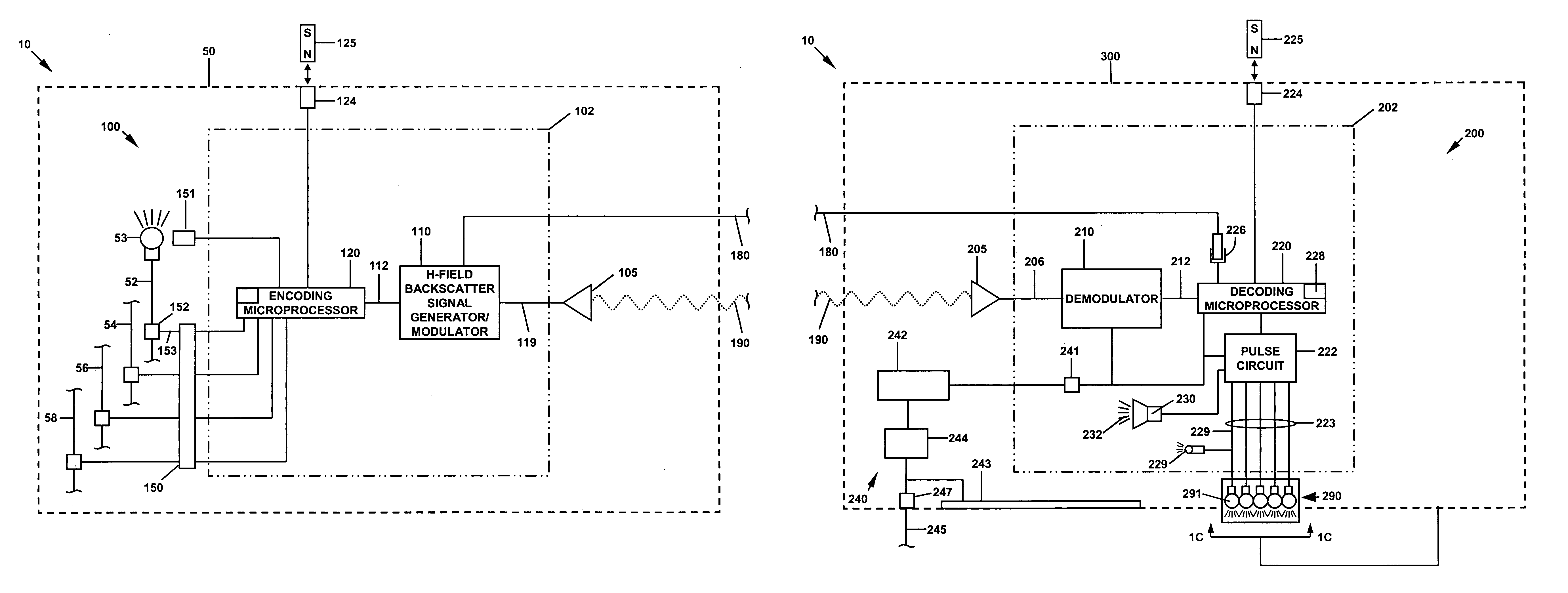
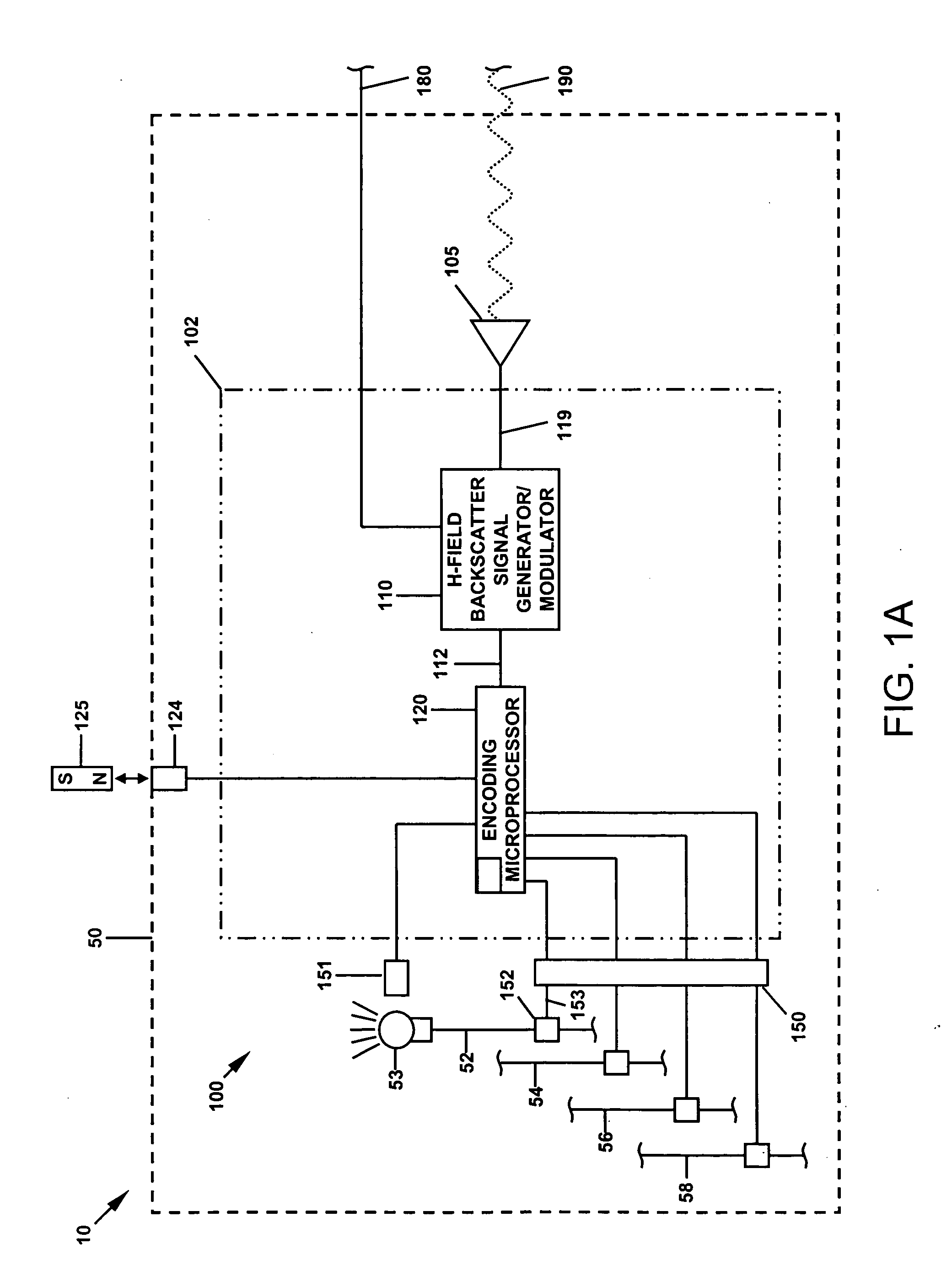
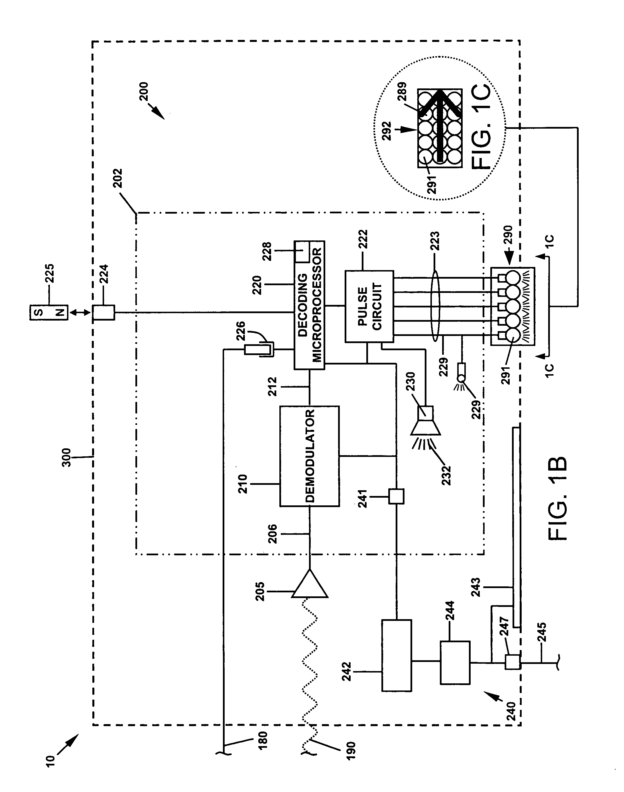
[0030] In accordance with one embodiment of this invention, there is further provided a safety lighting system for enhanced safety of a rider of a motorcycle, said system comprising an H-field backscatter generator disposed upon a motorcycle and adapted to receive at least one electrical signal indicating the application of electrical power to at least one light circuit of said motorcycle and comprising means for encoding and transmitting at least one encoded signal; a magnetic coupling receiver disposed on a safety helmet worn by said rider and adapted to receive said first encoded signal; and a light display electrically connected to said magnetic coupling receiver, said light display disposed upon the outside surface of said helmet and comprising at least one illuminatable lamp.
[0031] The lighting system described above is advantageous because it has very low power consumption, requires minimal space for components, is easily adapted to multiple motorcycles or other vehicles, and to multiple helmets or other placement locations for safety lighting, and can be provided at very low cost

Problems solved by technology

The safety risks associated with riding a motorcycle are higher than those driving an automobile.
First, motorcycles are smaller than automobiles, and other motorists often have a hard time seeing motorcycles on the roads.
Further, motorcycles are generally capable of higher rates of acceleration than automobiles causing other motorists to often lose track of the position of a nearby motorcycle.
Also, motorcycles are generally capable of higher rates of de-acceleration than automobiles, causing motorcycles to often be hit from behind by motorists that are unable to stop in time.
Finally, motorcycles lack the weight, protective structure and other safety devices (such as airbags) that are offered in automobiles.
The Hurt Report showed that approximately 75% of all motorcycle accidents involve a collision with another vehicle, and rear-end collisions are a significant risk.
Among their findings it was shown that “The failure of motorists to detect and recognize motorcycles in traffic is the predominating cause of motorcycle accidents.
Depending on the size and style of the motorcycle, the taillight is often small, relatively low to the ground and hard to see by other motorists.
Prior art helmet lighting systems have generally used lamps that are of lower than desirable intensity, since such systems are not able to provide enough power to operate higher intensity lamps for sustained periods with available on-board power sources.
In a battery operated system where the light is not in the operator's field of vision, it is not always possible to tell if the light is working.
The system of Whiting is relatively high in power consumption, is prone to interference, and has no provision for a single helmet to communicate with several transmitters.
These methods of activation are inherently prone to interference from stray light sources, such as infrared light emanating from heated surfaces, which are common in heavy vehicle traffic.
Such device is also prone to interference from the sun and other light sources
Prior art devices also use communication means that have relatively high power consumption; hence such devices must use lower power / lower brightness lighting as a tradeoff of sacrifice due to their communication power demands.

Method used


Image

  • Auxiliary safety light system
  • Auxiliary safety light system
  • Auxiliary safety light system

Examples


Embodiment Construction

[0046] For a general understanding of the present invention, reference is made to the drawings. In the drawings, like reference numerals have been used throughout to designate identical elements.

[0047] As used herein, the term “H-field backscatter generator” is meant to indicate a VLF (very low frequency) oscillator that produces low-frequency electromagnetic radiation in all directions.

[0048] Backscatter communication device and method technology has advanced considerably. For example, one may refer to U.S. Pat. No. 6,600,905 of Greef et al., “Communication system, interrogators and communication methods;” U.S. Pat. No. 6,466,771 of Wood, “Wireless communication system, radio frequency communications system, wireless communications method, radio frequency communications method, and backscatter radio frequency communications system;” and U.S. Pat. No. 6,459,726 of Ovard et al., “Backscatter interrogators, communication systems and backscatter communication methods,” the disclosure...


PUM


Abstract

A safety lighting system comprising an H-field backscatter generator adapted to receive at least one electrical signal indicating the application of electrical power to at least one light circuit and comprising means for encoding and transmitting at least one encoded signal; a magnetic coupling receiver located separately from the H-field backscatter generator and adapted to receive the first encoded signal; and a light display electrically connected to the magnetic coupling receiver, the light display comprising at least one illuminatable lamp.

Description

CROSS-REFERENCE TO RELATED PATENT APPLICATIONS [0001] This application is claims the benefit of the filing date of U.S. provisional patent application Ser. No. 60 / 514,849 filed Oct. 27, 2003, the disclosure of which is incorporated in its entirety by reference.[0002] This invention relates in one embodiment to a lighting system used to enhance safety in the operation of a motor vehicle, and more particularly to a remotely controlled light affixed to the helmet of a motorcyclist. FIELD OF THE INVENTION [0003] A remotely controlled safety lighting system integrated with a motorcycle and the helmet of a motorcyclist, or with a car, van, truck, trailer, bicycle or other vehicle to enhance the safety of the operation of the motorcycle or vehicle. BACKGROUND OF THE INVENTION [0004] A recent (1998) study by the National Highway Traffic Safety Administration (NHTSA) measuring the long-term effectiveness of center high mounted stop lamps in passenger cars and light trucks found that these li...

Claims


Application Information

Patent Timeline
Patent Type & Authority Applications(United States)
IPC IPC(8): B60Q1/26B60Q1/30
CPCB60Q1/2676B60Q2900/30B60Q1/305
Inventor WERNER, DAVID R.PALMITER, WAYNE R.ZIMA, DAVID
Owner THIRD EYE DESIGN INC
Learn More