Lay flat tubing

a technology of flat tubing and i.v., which is applied in the field of conducting fluid, can solve the problems of storing i.v. tubing with its ends open and exposed to the ambient environment, and achieving the effect of facilitating fluid delivery

Active Publication Date: 2006-10-12
MEDICAL SOLUTIONS
View PDF19 Cites 48 Cited by
  • Summary
  • Abstract
  • Description
  • Claims
  • Application Information

AI Technical Summary

Benefits of technology

[0012] Accordingly, it is an object of the present invention to provide lay flat tubing as a fluid conductor for transferring fluid to and from the body of a patient. The lay flat tubing facilitates fluid delivery to or removal from a patient's body at an access point, or can similarly effect the same function from a cavity or organ of a patient.

Problems solved by technology

Accordingly, first responders and hospitals require that large amounts of tubing be stored in anticipation of treatment, thereby creating an issue of storage space adequacy.
Hospitals and, more critically, ambulances have limited storage space for necessary medical supplies.
Similarly, storing I.V. tubing with its ends open and exposed to the ambient environment creates a contamination risk by unintentionally allowing micro-organisms, pyrogens, particulates, and other contaminants to enter and contact an inner surface of the intravenous tubing.
The application of multiple standalone lines coupled with intravenous tubes to treat a patient can be confusing to a caregiver and may result in incorrect deployment and treatment.
Moreover, manipulation of multiple lines can create a tangle and cause additional damage.
Such devices suffer from several drawbacks.
As a first responder, a caregiver may not have the time to properly setup and / or label each line administered.
However, gravitational forces may be insufficient to drive certain viscous liquids, such as blood, into the patient at the necessary flow rate.
This limits control accuracy of the liquid temperature, creating hotspots, i.e., sections of the tube being warmer than other sections of the tube, along the tube.

Method used


Image

  • Lay flat tubing
  • Lay flat tubing
  • Lay flat tubing

Examples


Embodiment Construction

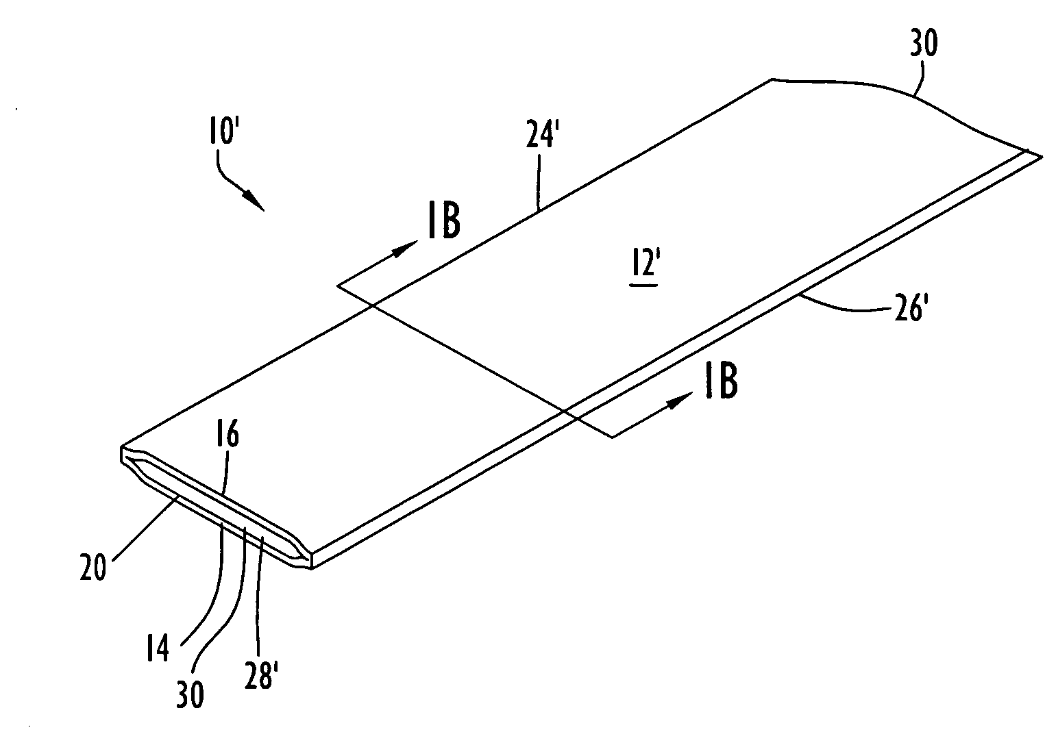
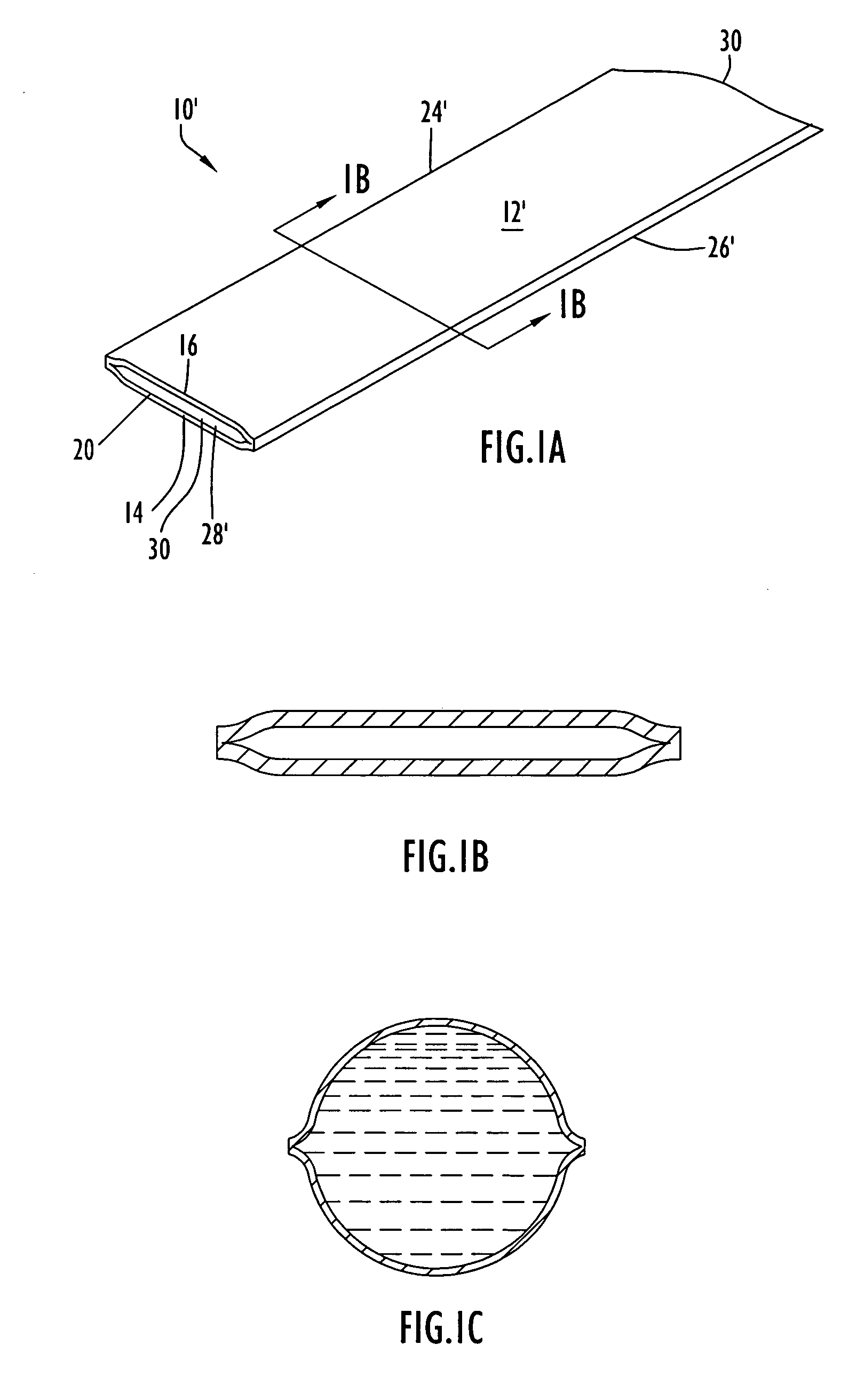
[0039] Referring to FIGS. 1A, 1B and 1C, a conduit unit representing one embodiment of the present invention is constructed of lay flat tubing comprising substantially flat tubing with a single lumen, or conduit, longitudinally disposed the length of the unit. FIGS. 1A and 1B illustrate the lay flat tubing 10 in its collapsed condition as is typical of the tubing during transport and / or storage. FIG. 1C illustrates the unit 10 inflated as by the passage of fluid therethrough. Lay flat tubing 10 has a top conduit layer 12 superimposed on a bottom conduit layer 14. Both layers 12, 14 have are generally shaped as elongated rectangles and are typically compressed together (i.e., the tubing is collapsed) when unit 10 is being stored or transported. It is to be noted that, for ease in understanding the drawings, there is a small space illustrated between layers 12 and 14; however, it will be recognized that in the collapsed state of the conduit the two layers are preferably in abutting, f...


PUM

PropertyMeasurementUnit
bursting strengthaaaaaaaaaa
internal pressureaaaaaaaaaa
pressureaaaaaaaaaa

Abstract

Lay flat tubing is used as a fluid conductor for transferring fluid to and from the body of a patient. The lay flat tubing lies flat or collapsed when not in use, utilizing minimal space during transportation and storage, but which expands to form a passage when used to conduct fluid. A plurality of lumens may be formed in the lay flat tubing. At least one lumen transports infused fluid end-to-end from a source to an entry site on a patient, or in the alternative from an entry site on or in a patient. All lumens are isolated with respect to each other in order to prevent crossover of fluid from one lumen to the other.

Description

BACKGROUND OF THE INVENTION [0001] 1. Technical Field [0002] The present invention pertains to methods and apparatus for conducting fluid to and from the body of a living being. In a particular embodiment, the present invention is directed toward methods and apparatus for infusing of one or more liquids into a patient and / or conducting such fluid(s) from a patient. The present invention is further directed to methods and apparatus for transferring information via a conductive material in a common structure with fluid-conductive tubing. [0003] 2. Discussion of Prior Art: [0004] Generally, intravenous (“I.V.”) solutions or other liquids are infused into a patient by disposing a liquid-filled bag containing the intravenous solution or other liquid on a support structure, e.g., a pole, that permits either gravitational forces or the application of additional pressure to direct liquid from the bag through a preformed cylindrical tube into a patient. [0005] Invariably, patients require in...

Claims


Application Information

Patent Timeline
Patent Type & Authority Applications(United States)
IPC IPC(8): A61M31/00B29C47/00D01D5/24B29C48/00B29C48/10B29C48/12
CPCA61M27/00A61M2027/004B29C47/00B29C47/0026B29C47/003Y10T29/49826B29C47/0059B29C47/0066B29L2023/007Y10T428/139B29C47/0054B29C48/00B29C48/10B29C48/12B29C48/0017B29C48/0019B29C48/0022
Inventor FARIES, DURWARD I. JR.
Owner MEDICAL SOLUTIONS
Why Eureka
Try Eureka