Method for fluid jet formation and apparatus for the same

a fluid jet and nozzle technology, applied in the direction of combustion types, combustion processes, burners, etc., can solve the problems of reducing the efficiency of the nozzle, and reducing the control of the cross-sectional geometry of the jet, so as to reduce the cost of jet fabrication and improve the control of the jet. the effect of cross-sectional geometry

Active Publication Date: 2007-03-06
GESKIN ERNEST +2
View PDF17 Cites 10 Cited by
  • Summary
  • Abstract
  • Description
  • Claims
  • Application Information

AI Technical Summary

Benefits of technology

[0007]Accordingly, it is an object of the present invention to provide a method and nozzle for forming a jet in which nozzle sealing is improved, the control of the jet cross-sectional geometry is improved, and the cost of jet fabrication is reduced, relative to the prior art.
[0008]Pursuant to the present invention, the sealing of the nozzle and the nozzle geometry are improved by forming the jet with an assembly of several parts so that a degree of elastic and plastic deformation of each part assures a desired hydraulic resistance of the parts boundary as well as desired opening geometry. The desired deformation of the parts is attained in the course of the nozzle assembly as well as by application of additional forces to the nozzle parts after assembly.
[0011]In order to minimize the hydraulic losses in the nozzle, the shape of the slot has the optimal curvature at the entrance and the exit as well as the optimal shape of the slot. The surface roughness of the jet forming opening is minimal. In order to attain desired nozzle geometry the parts forming the nozzle are assembled and then forced into the housing. The surface of the opening is processed so that its roughness and waviness are minimal.

Problems solved by technology

This mode of conversion, however, involves a significant loss of the jet's kinetic energy, which in turn, is a reduction in jet efficiency.
However, this nozzle cannot withstand a high pressure because it is composed of several elements with no reliable sealing between the elements.
This changes the jet geometry and thus its weakening.
However, the ultra precision polishing is a complicated and expensive procedure.
Moreover, the perfect attachment of two elements per se does not assure perfect sealing, especially at high fluid pressure.
However, this design does not provide a sealing of contact surfaces, and thus cannot be used at high pressure.
However, it is difficult to create the micron sized channels.
Moreover, this design again does not assure sealing at high fluid pressure.

Method used


Image

  • Method for fluid jet formation and apparatus for the same
  • Method for fluid jet formation and apparatus for the same
  • Method for fluid jet formation and apparatus for the same

Examples


Embodiment Construction

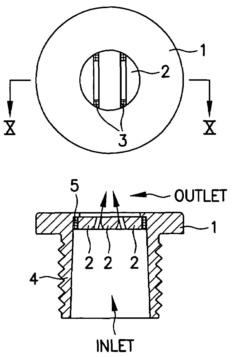
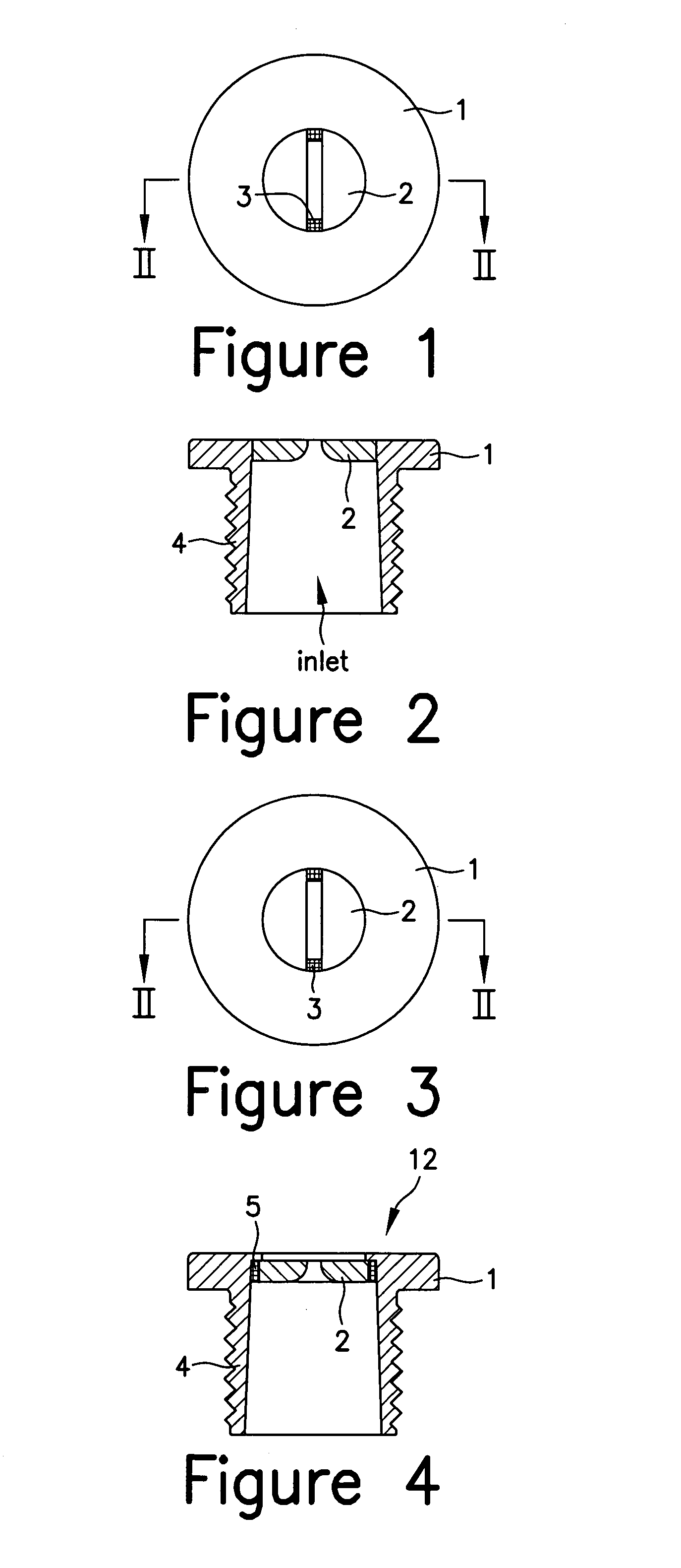
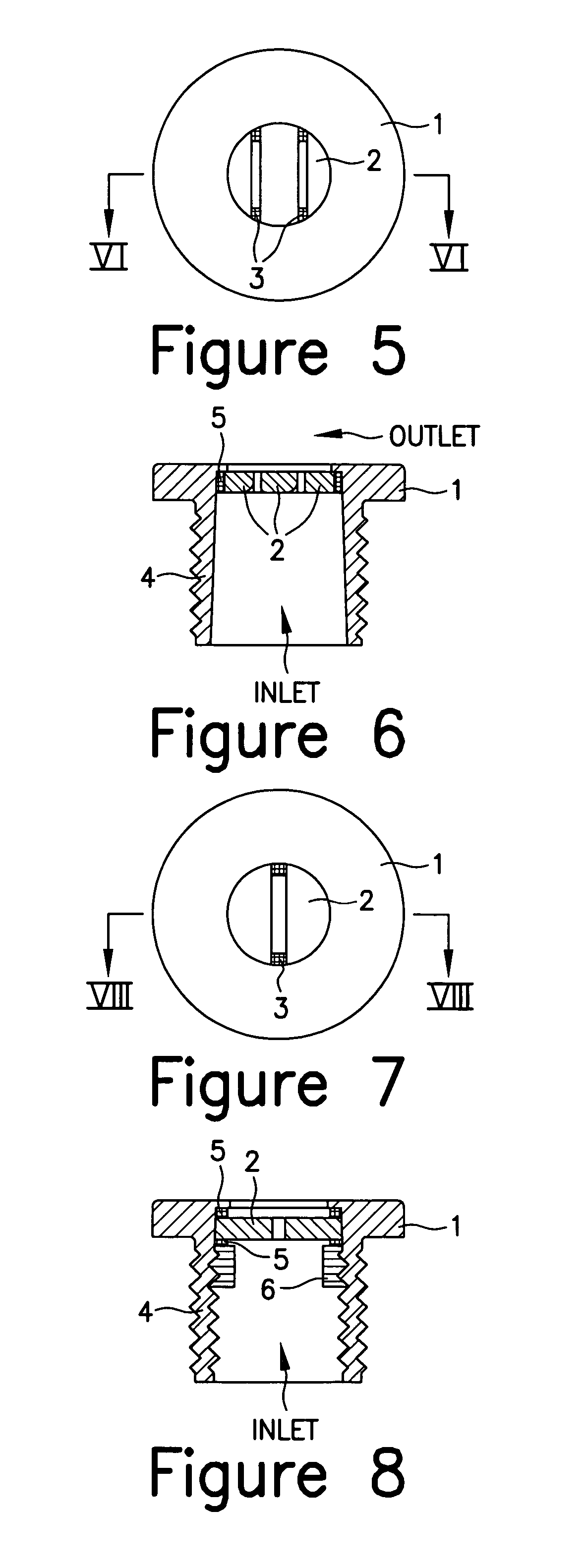
[0032]FIGS. 1 and 2 show a force-fit nozzle comprising a housing 1, two force-fit parts 2 having a cross section, e.g. segment, equal to the cross section of the housing interior and separated by a rectangular spacer seal 3. The parts 2 are force-fit inserted into the housing 1. The fluid enters the nozzle via an inlet. The housing has a fitting 4 that connects the nozzle with a pipeline. The parts can be of any suitable material, such as steel, ceramic, carbon fiber, diamond, etc.

[0033]The spacer seal material can be a brazable material that is later heated after being placed between the parts 2 so as to melt and subsequently solidify to form a seal. The material can be melted by induction heating, or by another other suitable heating source.

[0034]The nozzle generates a plane stream with an aspect ratio changing from 1 to 100,000 and generates slot jets having a thickness from several nanometers to several millimeters. The shape of the slot jet is determined by the thickness (for e...


PUM


Abstract

A nozzle having a housing and an assembly including at least two conjugated parts separated by a spacer seal. The assembly is arranged in the housing so as to form a nozzle outlet. At least one of he housing, the parts, and the spacer seal are deformable so as to define a geometry of the nozzle outlet and seal surfaces between the parts and the spacer seal and between the parts and the housing.

Description

BACKGROUND OF THE INVENTION[0001]The present invention relates to a method for forming a fluid jet, and a nozzle for producing the jet. A fluid jet is normally produced by accelerating the fluid.[0002]The most common method of fluid acceleration is the variation of the fluid stream cross section. The most common apparatus for implementing this method is a nozzle. A traditional nozzle design is a solid part with a channel where the fluid acceleration occurs. The advantage of this apparatus is complete sealing of the channel and simplicity of formation of a conical and cylindrical channel. In a number of applications (see for example, E. S. Geskin, B. Goldenberg Book: “Particals on Surface 8: Detection, Adhesion and Removal” Editor: K. L. Mittal, VSP Utrecht, Boston, 2003, pp. 141–151, and E. S. Geskin, B. Goldenberg, 2003 WJTA American Waterjet Conference, Aug. 17–19, 2003, Houston, Tex.) the circular cross section of the jet is not optimal. In such applications as, for example, cutt...

Claims


Application Information

Patent Timeline
Patent Type & Authority Patents(United States)
IPC IPC(8): B05B1/00B05B1/30B05B1/02B05B1/04B05B1/14B05B1/26B05B7/04
CPCB05B1/02B05B1/042B05B7/04B05B1/26B05B1/14
Inventor GESKIN, ERNESTGOLDENBERG, BORISURSIC, THOMAS
Owner GESKIN ERNEST
Why Eureka
Try Eureka