Click on the blue label to locate the original text in one second.
Reading with bidirectional positioning of images and text.
Examples
Example
DETAILED DESCRIPTION OF THE DRAWINGS
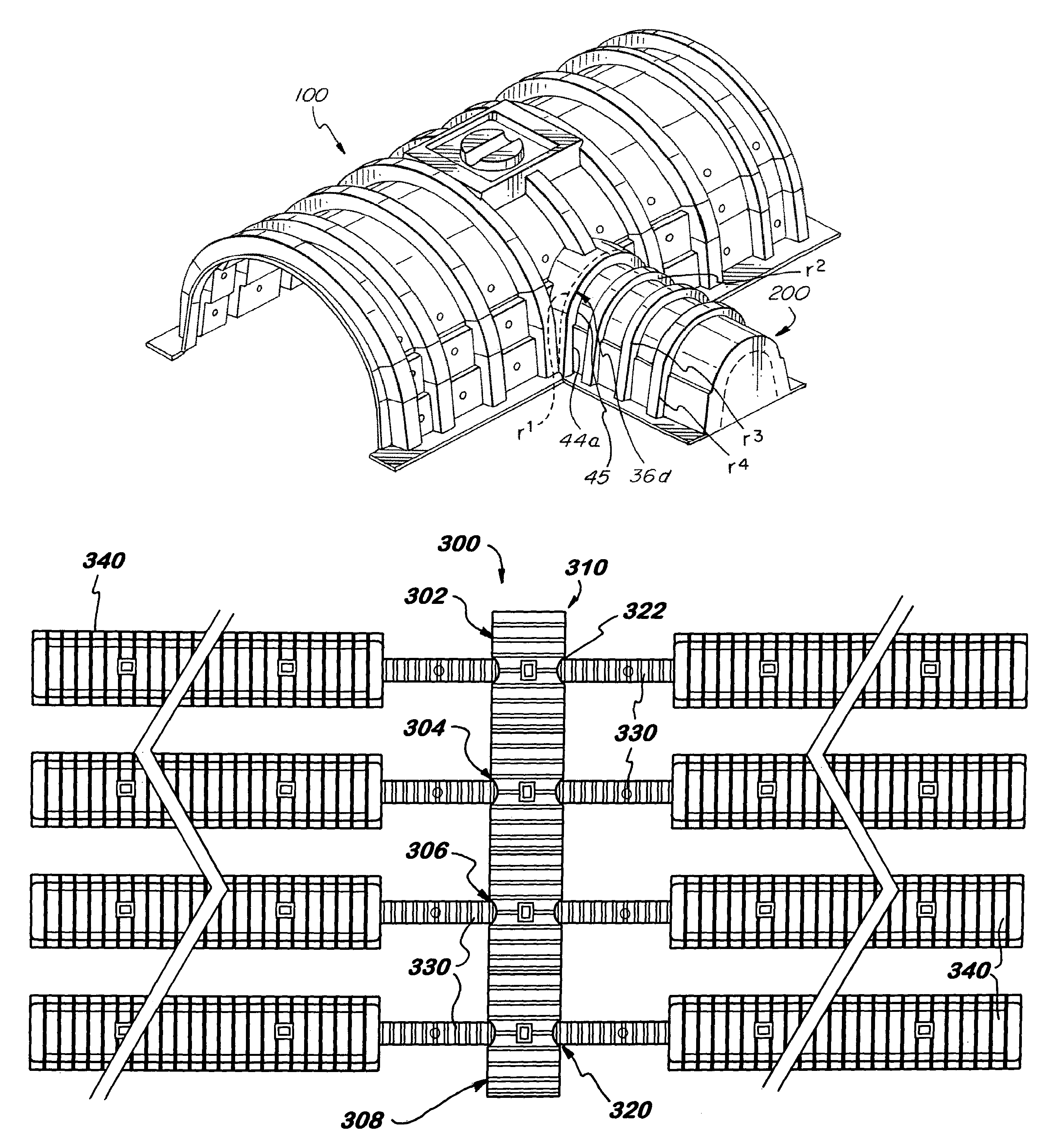
[0020]Preferred embodiments of the present invention are described herein with particular references to the drawings. The present invention disclosure consists basically of two parts, i.e., the first part is regarding liquid dispensing chambers which is described in association with FIGS. 1–8, and the other part is regarding related liquid drainage systems utilizing the dispensing chambers of the invention which is described in association with FIGS. 9–12. The invention is particularly useful for and thus described primarily in association with storm-water handling and / or dispensing system. However, it is to be noted that the invention may be applicable to any kinds of wastewater handling systems such as commercial or domestic septic systems.
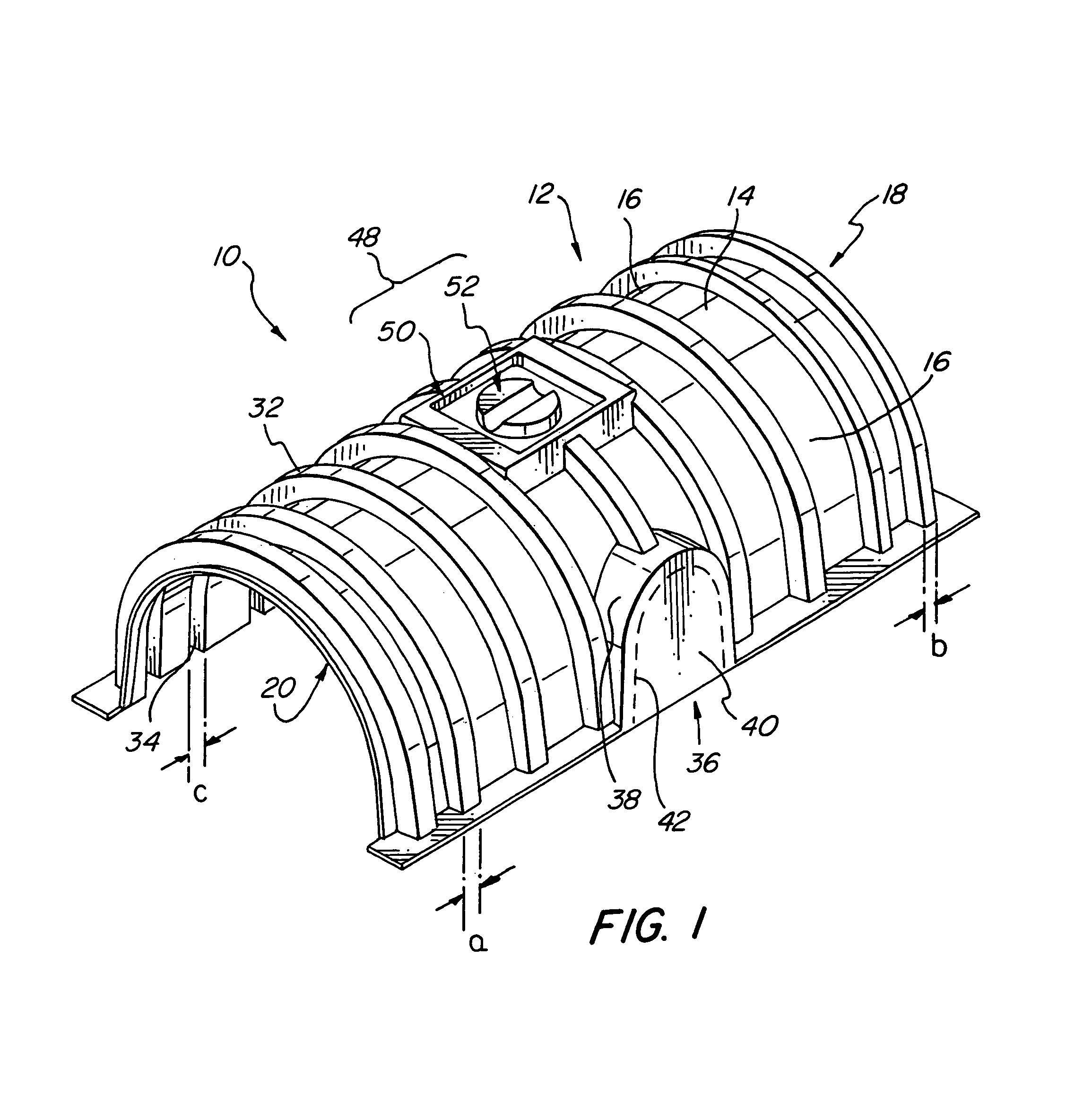
[0021]FIG. 1 illustrates a preferred embodiment of the liquid dispensing chamber of the present invention. Liquid dispensing chamber 10 has a generally arch-shaped configuration and is preferably made of plas...
PUM
Abstract
A liquid dispensing chamber for use with a drainage system for gathering and dispensing liquids to the ground is disclosed, which includes an elongated wall body having a generally arch-shaped cross-sectional configuration with a top wall portion and a pair of side wall portions thereby defining an enlarged enclosure therein, the elongated wall body including a first end portion and a second end portion, at least one of the end portions defining therein an axial opening to allow axial flow of liquids there-through, a plurality of circumferential reinforcing members disposed along the circumference of the elongated wall body for reinforcing structural strength thereof, and at least one side desk member disposed at least a location in the side wall portions of the elongated wall body. The at least one side deck member selectively includes a lateral opening therein for connecting a connection conduct thereto. Liquid drainage systems utilizing the liquid dispensing chambers of the invention is also disclosed.
Description
FIELD OF THE INVENTION[0001]The present invention relates to a system for dispensing liquids and, more particularly, to liquid dispensing chambers and a liquid drainage system using the liquid dispensing chambers for gathering and dispensing liquids to the ground.BACKGROUND OF THE INVENTION[0002]Various methods, systems and apparatus are known to handle wastewater and / or storm water. Culverts, catch basins, storm sewers and out falls have been used for handling storm water. Although such systems provide substantial advantages over direct discharge into the existing water body, they preclude other uses of the land. This is particularly important where land values are high such as in urban, residential and industrial areas. In addition, such known approaches have adverse environmental effects, for example, lowering of local water tables when water is diverted from percolating into the earth.[0003]Consequently, it is desirable to direct rain or storm water into the earth. This has typi...
Claims