

Plate heat exchanger and method for manufacturing of a plate heat exchanger
- Summary
- Abstract
- Description
- Claims
- Application Information
AI Technical Summary
Benefits of technology
Problems solved by technology
Method used
Image

Examples
Embodiment Construction
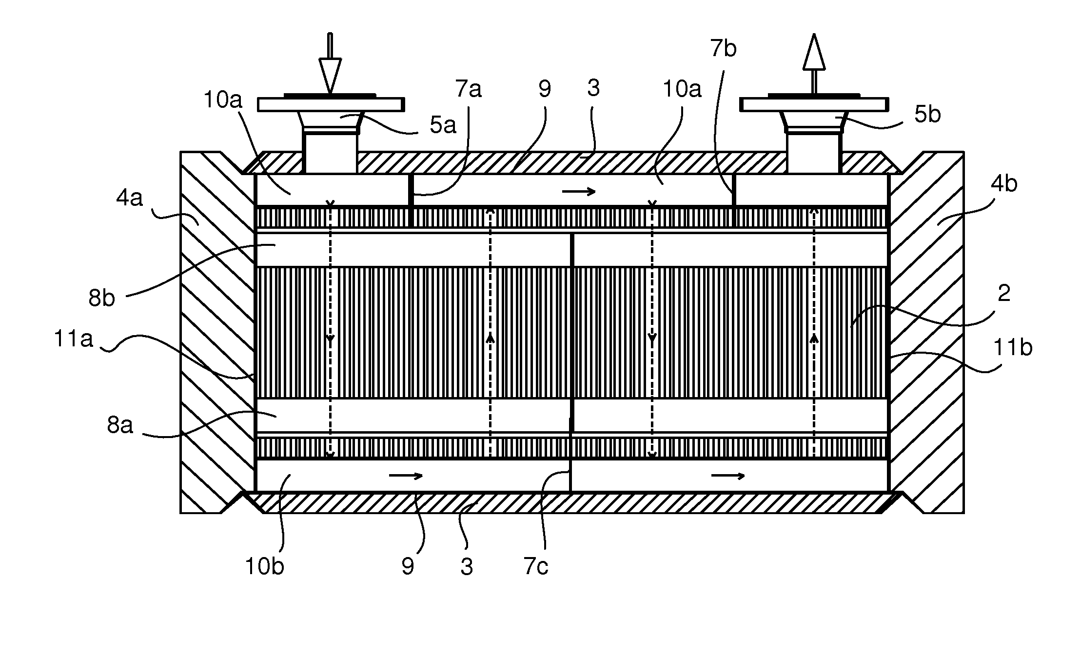
[0005]It is an object of the present invention to present a structure for a plate heat exchanger, which reduces or even eliminates the above-mentioned problems appearing in prior art.
[0006]It is an object of the invention to present a structurally simple plate heat exchanger, where the heat exchange surfaces can be utilised more efficiently than in previously known plate heat exchangers. It is also an object of the invention to reduce manufacturing costs of a plate heat exchanger.
[0007]It is an object of the invention to provide a plate heat exchanger, which is highly resistant to pressure.
[0008]The plate heat exchanger and method for manufacturing a plate heat exchanger according to the invention are characterised in what is presented in the enclosed independent claims.
[0009]The other, dependent claims present some preferred embodiments of the invention.
[0010]The embodiments and advantages mentioned in this text are in suitable parts applicable to both a plate heat exchanger and a ...
PUM
| Property | Measurement | Unit |
|---|---|---|
| Time | aaaaa | aaaaa |
| Thickness | aaaaa | aaaaa |
| Thickness | aaaaa | aaaaa |
Abstract
Description
Claims
Application Information