
Electrical plug connector

Active Publication Date: 2019-07-11
ADVANCED CONNECTEK INC
View PDF2 Cites 0 Cited by
  • Summary
  • Abstract
  • Description
  • Claims
  • Application Information

AI Technical Summary

Benefits of technology

The invention provides an improved electrical plug connector with a hook that is resistant to deformation and has improved resilience performance. The hook has a crescent shape and is rotatable relative to each other. The first and second buckle structures prevent excessive deformation of the elastic arm and prevent the hook from detaching from the recessed groove. The mating between the electrical plug and receptacle connectors is achieved by an engagement manner, preventing unintentional detachment. Overall, the invention ensures safe and reliable electrical connection.

Problems solved by technology

However, the electrical plug connector known to the inventor does not have a stopping structure on the hook.
Hence, the resilience performance of the hook is worsened.

Method used


Image

  • Electrical plug connector
  • Electrical plug connector
  • Electrical plug connector

Examples


first embodiment

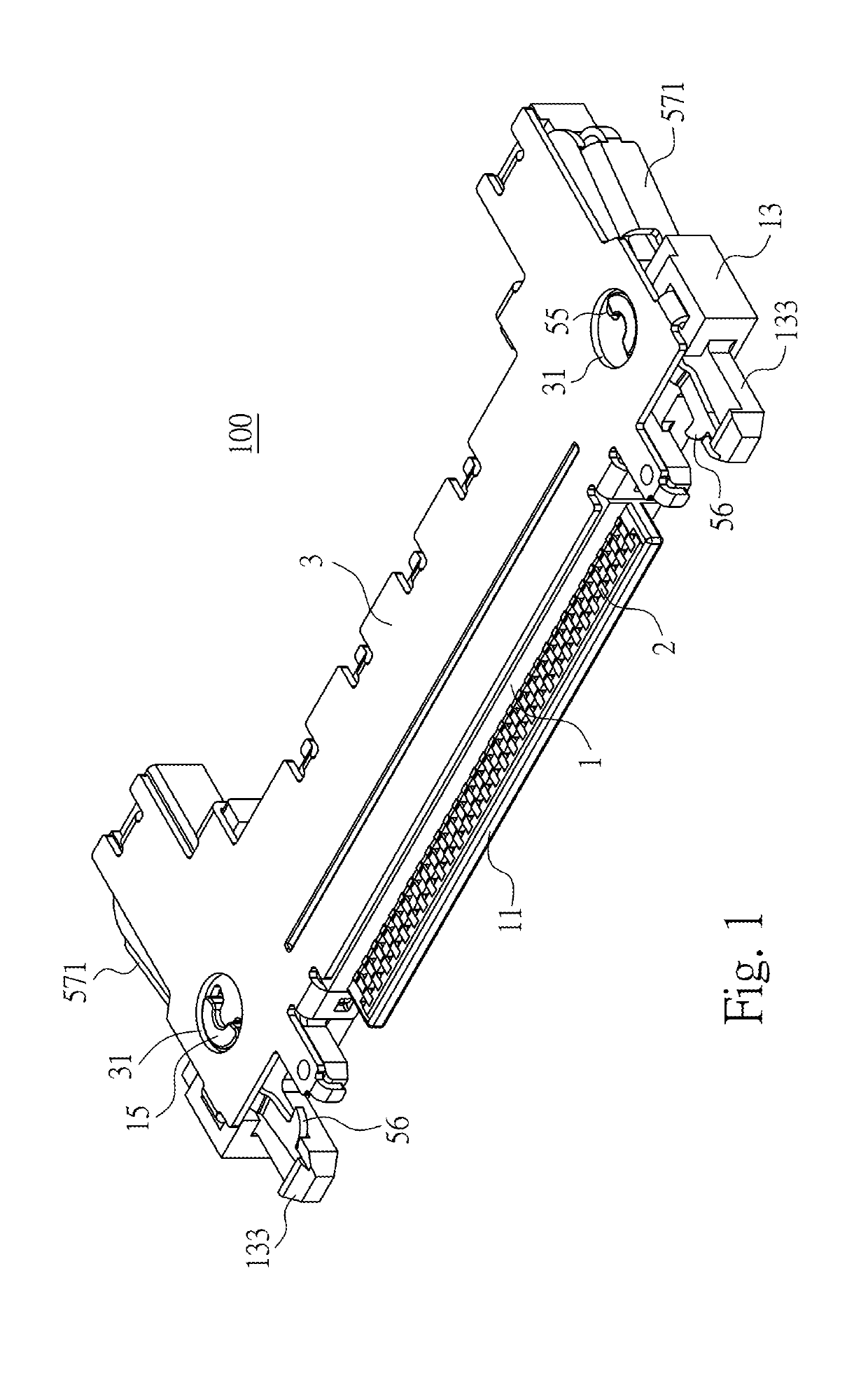
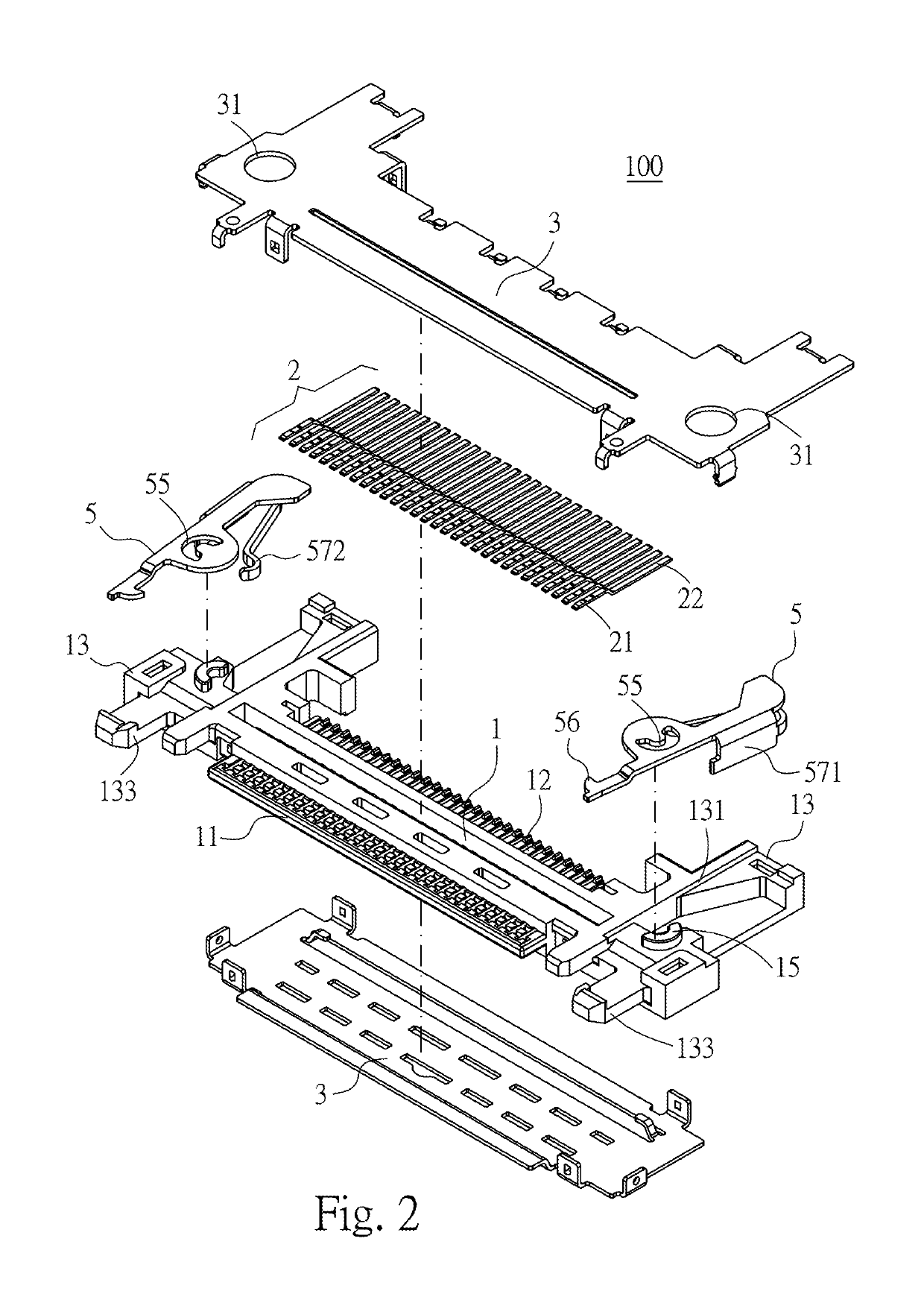
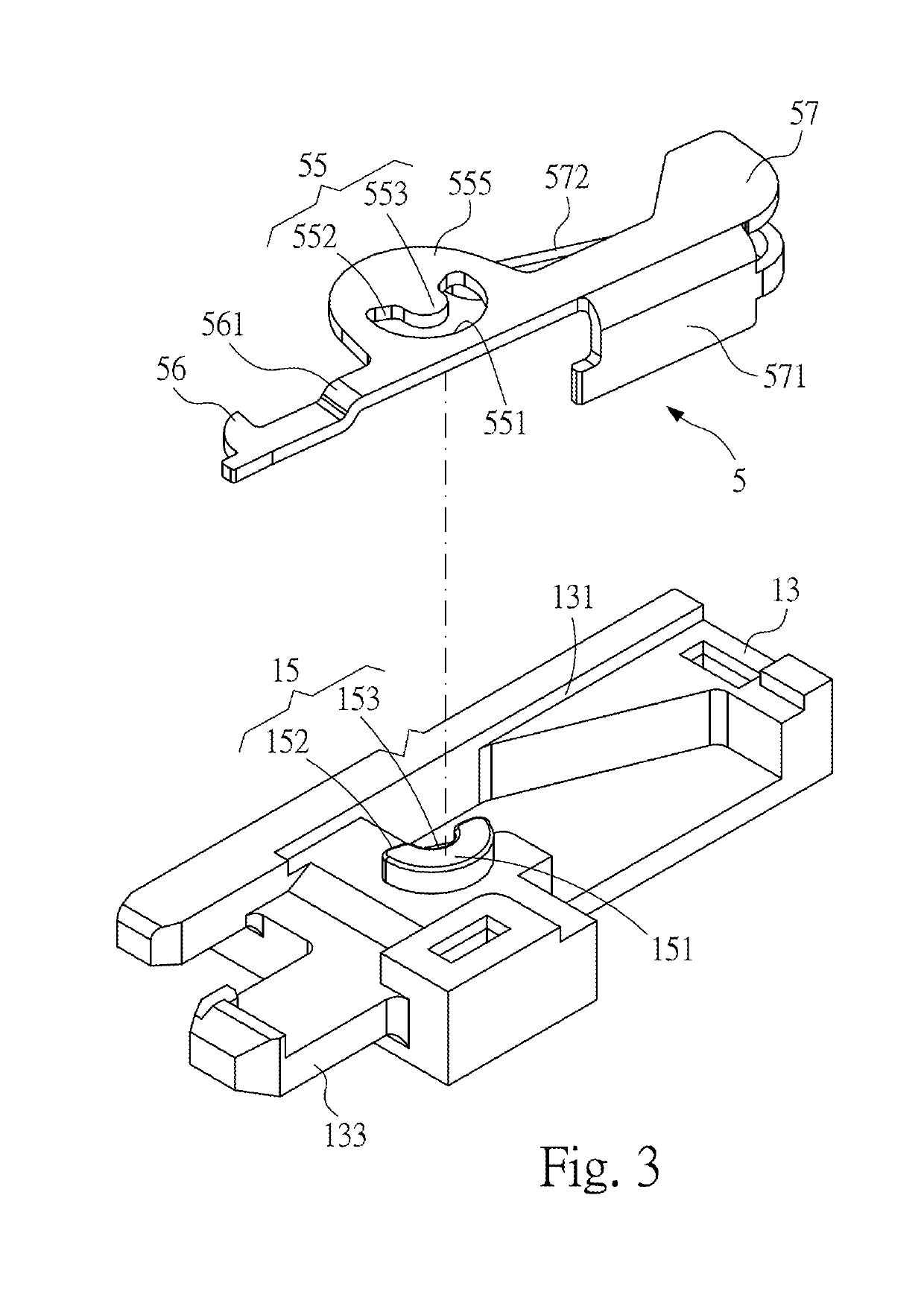
[0030]Please refer to FIGS. 1 to 3, illustrating an electrical plug connector 100 according to the instant disclosure. FIG. 1 illustrates a perspective view thereof, FIG. 2 illustrates an exploded view thereof, and FIG. 3 illustrates a partial exploded view thereof.

[0031]In this embodiment, the electrical plug connector 100 is provided with a flexible flat cable (FFC) (not shown). In this embodiment, the electrical plug connector 100 comprises an insulated housing 1, a plurality of contact terminals 2, an outer shell 3, and a plurality of hook members 5.

[0032]Please refer to FIGS. 1 to 3. In this embodiment, the insulated housing 1 is an elongated plate. An insertion part 11 is a plate-shaped part that extends from the front surface of a body of the insulated housing 1 and has a plurality of terminal grooves formed on its upper surface, and the insertion part 11 is adapted to be inserted into an insertion opening of an electrical receptacle connector 200 (as shown in FIG. 8). A cabl...

second embodiment

[0048]Please refer to FIG. 4. In the second embodiment, the inner surface of the recessed groove 131 of each of the side arms 13 comprises a first curve portion 151 and two first abutting portions 152 together forming a hole. Namely, the first buckle structure 15 is a through hole. In this embodiment, the first buckle structure 15 forms a crescent-shaped hole (or called C-shaped hole). The first buckle structure 15 comprises the first curve portion 151, the two first abutting portions 152 at two ends of the first curve portion 151, and a first shaft portion 153 at an inner side of the first curve portion 151. The first shaft portion 153 is a protruding portion. From a top view of the first buckle structure 15, the arc length of the first buckle structure 15 is greater than the perimeter of a half circle, but embodiments are not limited thereto. In some embodiments, the arc length of the first buckle structure 15 may be equal to or less than the perimeter of a half circle.

[0049]Pleas...


PUM


Abstract

An electrical plug connector includes an insulated housing, contact terminals held in the insulated housing, an outer shell covering the insulated housing, and hook members. First buckle structures are at side arms at two sides of the insulated housing. Each of the hook members includes a second buckle structure mating with the corresponding first buckle structure. The buckle structures are of crescent shapes and mated with each other. When the press portion of the hook member is pressed by an excessive force, the first / second buckle structure stops the second / first buckle structure to prevent the elastic arm of the hook member from deforming. When the elastic arm is bounced back excessively, the first / second buckle structure stops the second / first buckle structure to prevent the hook member from detaching off the side arm.

Description

CROSS-REFERENCE TO RELATED APPLICATION[0001]This non-provisional application claims priority under 35 U.S.C. § 119(a) to Patent Application No. 201820038374.6 filed in China, P.R.C. on Jan. 10, 2018, the entire contents of which are hereby incorporated by reference.FIELD OF THE INVENTION[0002]The instant disclosure relates to an electrical connector, and more particular to an electrical plug connector.BACKGROUND[0003]Flexible flat cable (FFC) has advantages of high flexibility and good performance in signal transmission and is widely utilized in different electronic products. The characteristics of the flexible flat cable allow the space inside the electronic product to be utilized in a flexible manner. By inserting an end portion of the flexible flat cable into an electrical plug connector, the electrical plug connector at one location in the electronic product can be mated with an electrical receptacle connector at another location in the electronic product.[0004]An electrical plu...

Claims


Application Information

Patent Timeline
IPC IPC(8): H01R13/627H01R13/506H01R13/405
CPCH01R13/6273H01R13/506H01R13/405H01R13/6275
Inventor HOU, PIN-YUANXIAO, SHUANG-XIYEH, YU-CHAI
Owner ADVANCED CONNECTEK INC
Learn More