
An industrial textile

Active Publication Date: 2019-12-19
VALMET TECH OY
View PDF0 Cites 0 Cited by
  • Summary
  • Abstract
  • Description
  • Claims
  • Application Information

AI Technical Summary

Benefits of technology

The industrial textile has a design that allows it to absorb a lot of washing liquid and easily spread it throughout. After washing, the textile is better at collecting dirt and residues. Additionally, the design reduces damage to the yarns caused by the washing liquid. The use of a double warp made from overlapping yarns makes the textile stronger and more resistant to wear. This design also makes the textile more stable, as the overlapping yarns offset one another. When a seam is formed to join the two ends of the textile, the strength of the seam is also increased due to the offset warp yarns.

Problems solved by technology

Further, according to an idea the first surface of the industrial textile has such topography that dirt does not easily fill up the surface.

Method used


Image

  • An industrial textile
  • An industrial textile

Examples


Embodiment Construction

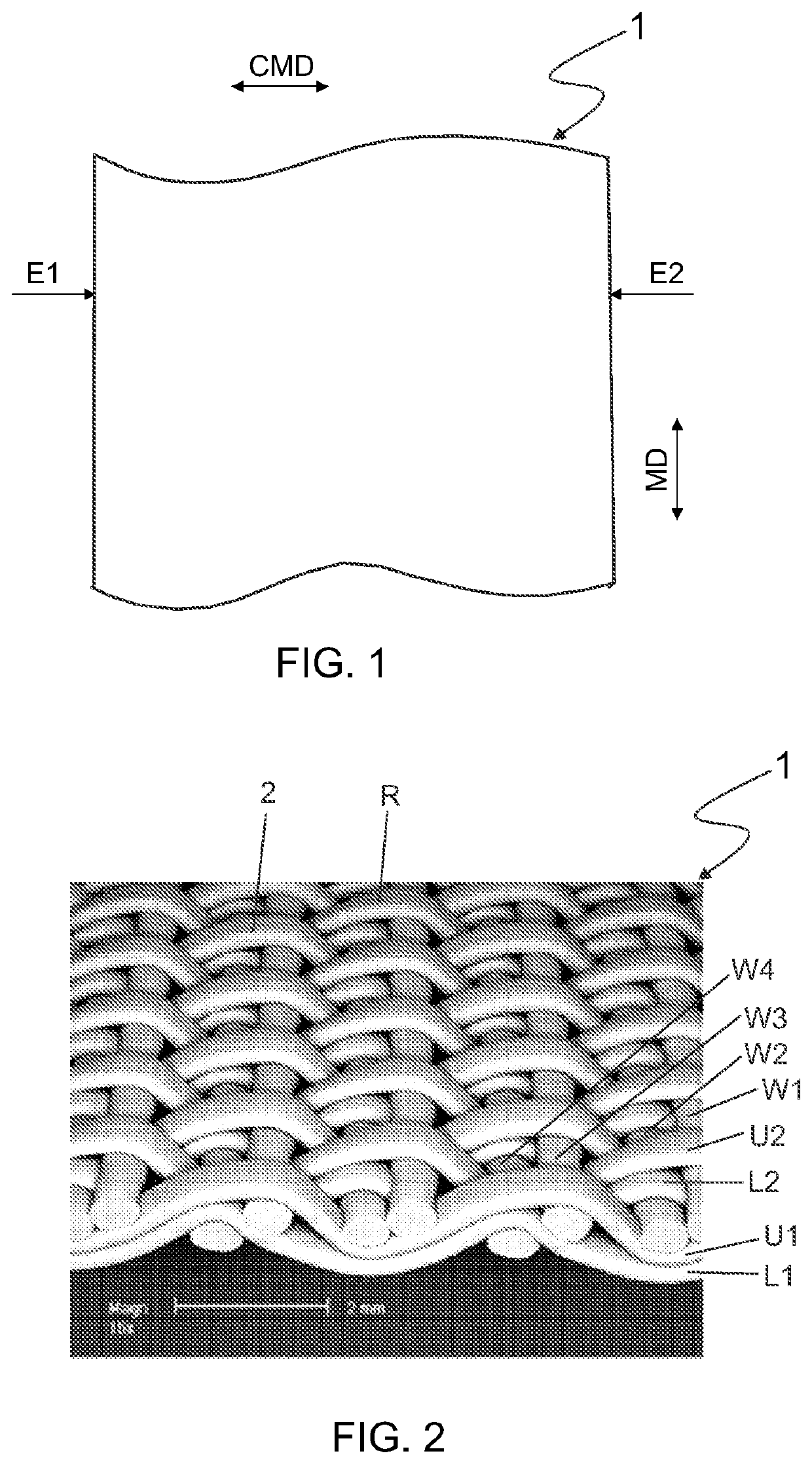
[0024]FIG. 1 shows an industrial textile 1 from above. A first surface of the industrial textile 1 is up. The industrial textile 1 has a cross machine direction CMD and a machine direction MD. The cross machine direction CMD corresponds to a weft direction and the machine direction corresponds to a warp direction, i.e. a longitudinal direction of the industrial textile 1. The industrial textile 1 extends from a first edge E1 to a second edge E2.

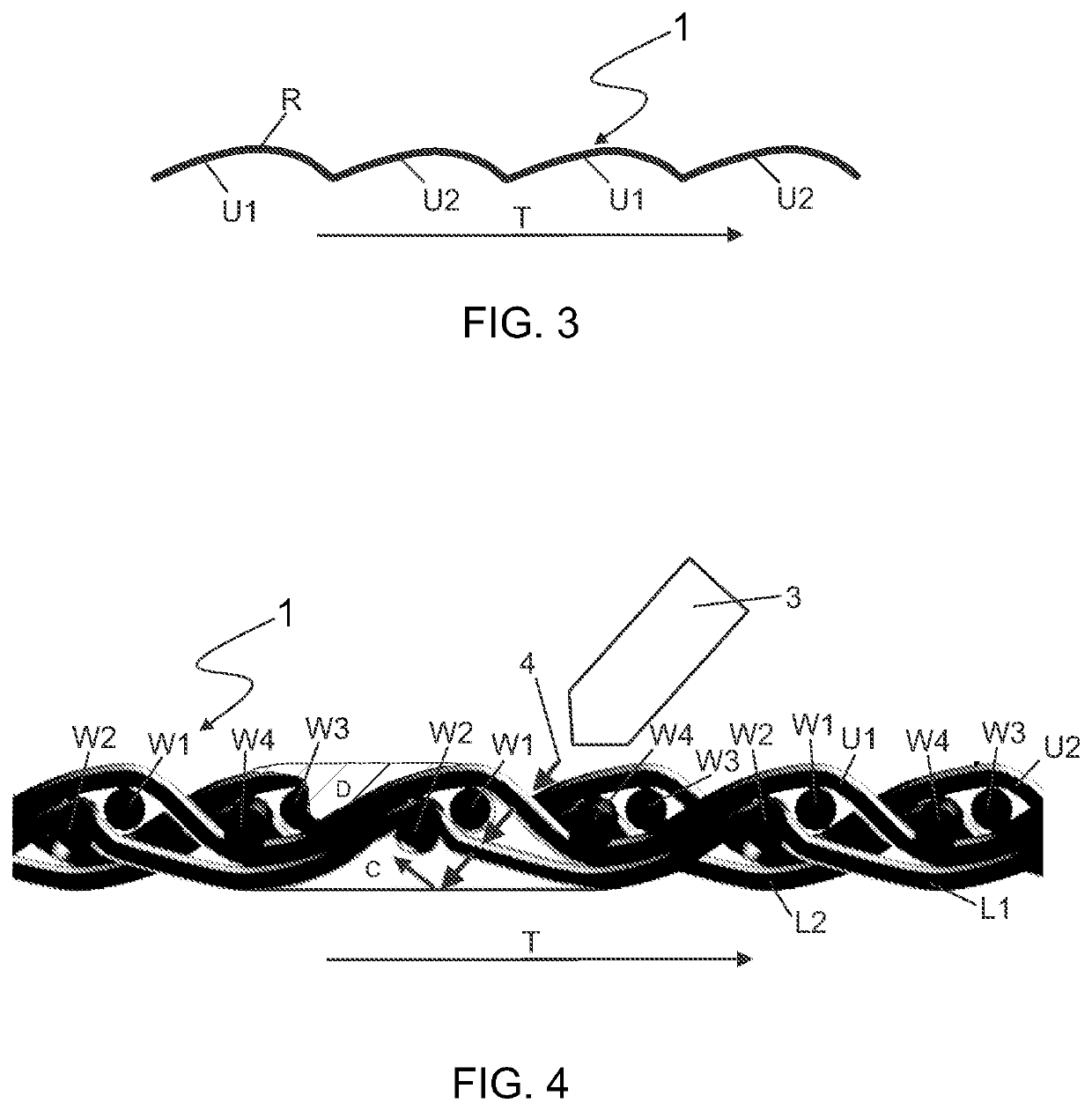
[0025]FIG. 2 shows an industrial textile 1 in a perspective view with the first surface up. The industrial textile 1 comprises yarns U1 and U2 of the first warp, and yarns L1 and L2 of the second warp. The yarns U1 and Ll are essentially one upon the other but the yarns U2 and L2 are offset, i.e. the yarn U2 is shifted laterally in respect of the yarn L2. However, it is possible that also the yarns U1 and L1 are offset. The yarns U1, U2, L1 and L2 are usually monofilament yarns and they may be flat yarns. The warp cover of each warp is prefer...


PUM


Abstract

The present invention relates to an industrial textile (1) having a longitudinal direction (MD) and a cross direction (CMD) and a first surface and a second surface, the industrial textile (1) extending in the cross direction from a first edge (E1) to a second edge (E2). The industrial textile (1) comprises a double warp which comprises a first warp comprising first machine direction yarns (U1, U2) and a second warp comprising second machine direction yarns (L1, L2). The yarns (U1, U2) of the first warp are arranged in above the yarns (L1, L2) of the second warp and the yarns of the first warp are at least partially offset in respect of the yarns of the second warp. The industrial textile comprises a weft comprising cross machine direction yarns (W1, W2, W3, W4). The yarns (U1, U2) of the first warp and the yarns (W1, W2, W3, W4) of the weft bind themselves to each other according to a first predetermined pattern and the yarns (L1, L2) of the second warp and the yarns (W1, W2, W3, W4) of the weft bind themselves to each other according to a second predetermined pattern. The first predetermined pattern and the second predetermined pattern form a textile structure which comprises the cross machine direction yarns (W1, W2, W3, W4) at least on two different levels in the thickness direction of the industrial textile (1).

Description

FIELD OF THE INVENTION[0001]The present invention relates to an industrial textile having a longitudinal direction and a cross direction and a first surface and a second surface. The industrial textile extends in the cross direction from a first edge to a second edge.BACKGROUND OF THE INVENTION[0002]The known industrial textiles have weft yarns in one plane in their thickness direction which maximizes the area which is perpendicular to a jet of a high pressure washing liquid and thus, the jet cannot penetrate in the textile sufficiently. This results in an inadequate washing result and damaged yarns.[0003]The inadequate washing result has led to higher pressures (500 to 600 bar) during the washing process which makes the damages of the yarns even worse. The fibrils of the damaged yarns fill the structure between the yarns of the industrial textile, thus decreasing the air permeability of the textile. This may lead to runnability problems. Further, the machines for high pressure wash...

Claims


Application Information

Patent Timeline
IPC IPC(8): D03D1/00D03D1/02
CPCD21F1/10D21F1/0036D03D1/0094D03D1/02D21F7/08D03D3/04Y10S162/902D21F1/0027D21F7/10
Inventor ENQVIST, RAUNOPAAVOLAINEN, JUHA
Owner VALMET TECH OY
Learn More