Power generation unit and fuel cell

Inactive Publication Date: 2005-09-01
SONY CORP
View PDF3 Cites 5 Cited by
  • Summary
  • Abstract
  • Description
  • Claims
  • Application Information

AI Technical Summary

Benefits of technology

[0017] According to the fuel cell of the present invention, since flow rates of the fluid flowing through the individual flow paths of the power generation unit is uniform, the fuel cell composed of the power generation unit has equal flow rates of the fluid flowing throug

Problems solved by technology

Downsizing of the fan, however, increases an occupational ratio of the motor provided at the center portion of the housing, and this undesirably reduces a blas

Method used


Image

  • Power generation unit and fuel cell
  • Power generation unit and fuel cell
  • Power generation unit and fuel cell

Examples


Example

[0030] The following paragraphs will describe in detail a power generation unit, and a fuel cell comprising the power generation unit of the present invention, referring to the attached drawings. It is to be understood that the present invention is by no means limited to the following description, and allows any proper modifications without departing from the spirit of the invention.

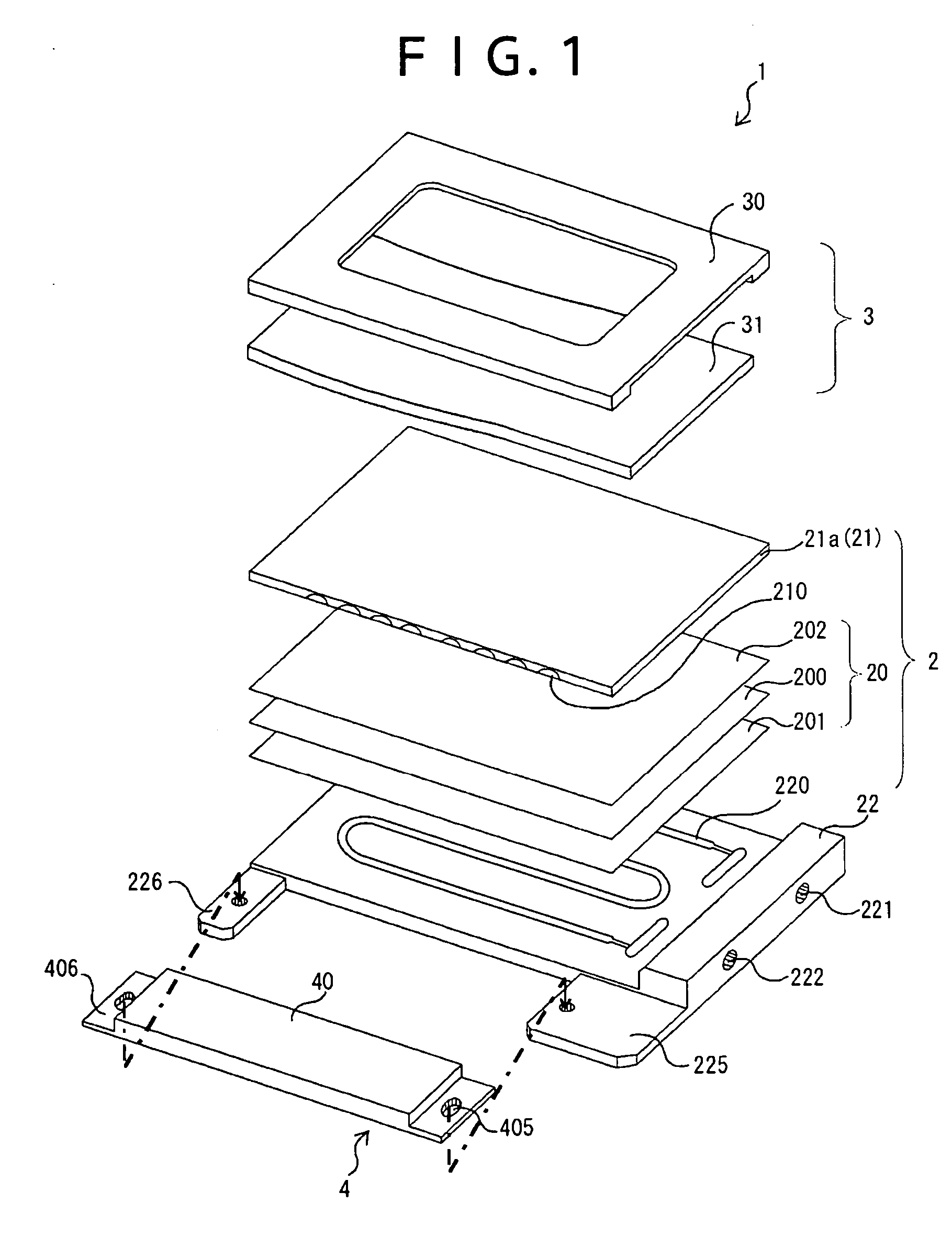
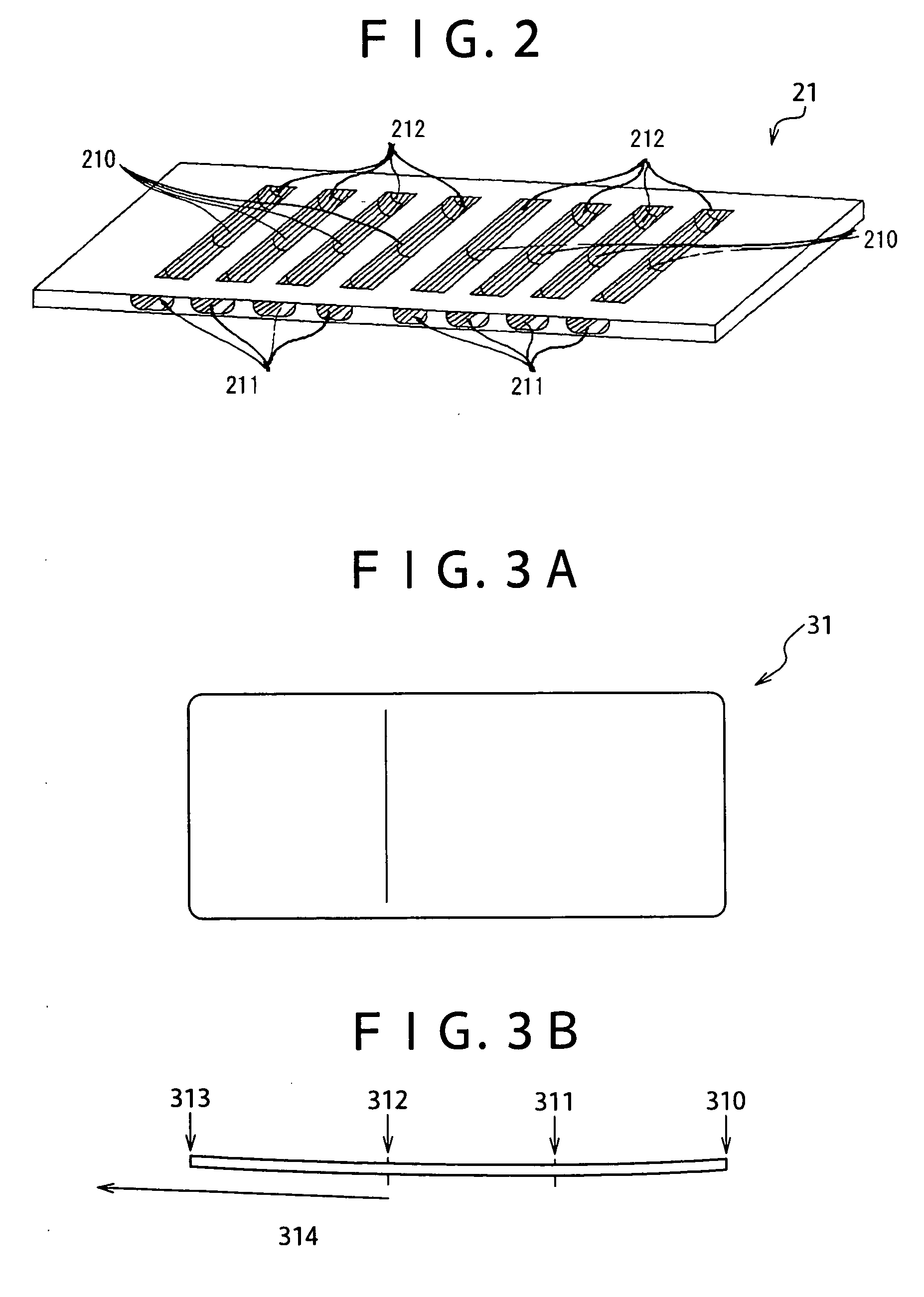
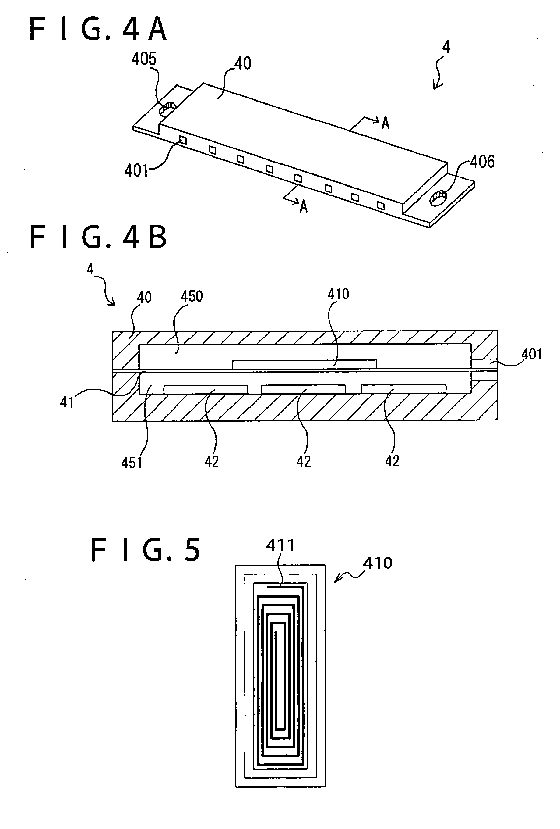
[0031]FIG. 1 shows an exploded perspective view showing components composing the power generation unit of the present invention. The power generation unit 1 of the present invention is configured as having a power generation cell 2, a fastening unit 3 and a fluid conveyance unit 4. In the power generation cell 2, a joint component 20, having an electrolyte 200 sandwiched between electrodes 201, 202, is held between a flow path forming component 21 having oxidant gas flow paths 210 allowing the air to flow therethrough and a base 22 having a fuel gas flow path 220 allowing hydrogen gas to flow therethrou...


PUM


Abstract

The present invention is to provide a power generation unit successful in equalizing flow rates of fluids flowing through individual flow paths of a power generation cell, and is to provide a fuel cell which can flexibly be adapted to required power generation capacity, geometry. The power generation unit of the present invention comprises a power generation cell which is composed of a joint component of a pair of electrodes and an electrolyte component held between the electrodes, and a flow path forming component having a flow path allowing a fluid supplied to the joint component to flow therethrough; and a fluid conveyance apparatus having an opening commonly functioning as an intake port and a discharge port of the fluid. This enables equalizing of the flow rates of the fluid flowing in the flow path, resulting in equalization of flow rates of the fluids flowing through the individual flow paths.

Description

CROSS REFERENCES TO RELATED APPLICATIONS [0001] The present document is based on Japanese Priority Document JP 2004-052873, filed in the Japanese Patent Office on Feb. 27, 2004, the entire contents of which being incorporated herein by reference. BACKGROUND OF THE INVENTION [0002] 1. Field of the Invention [0003] The present invention relates to a power generation unit, and a fuel cell having the power generation unit mounted thereon. [0004] 2. Description of Related Art [0005] A fuel cell is a power generation element which generates electric power by allowing a fuel gas, such as hydrogen gas, and an oxidant gas, such as oxygen gas, to electrochemically react. The fuel cell has been attracting a public attention as an environmentally-clean power generation element, because water is an only product of the power generation, so that efforts have been made typically on its use as a drive power source for driving automobiles. [0006] The fuel cell can be classified by electrolyte into va...

Claims


Application Information

Patent Timeline
IPC IPC(8): H01M8/02H01M2/00H01M2/02H01M2/14H01M8/04H01M8/10H01M8/24
CPCH01M8/0247Y02E60/50H01M8/248H01M8/04089
Inventor OTSUKA, KAZUHIKO
Owner SONY CORP
Why Eureka
Try Eureka