

Heater Having Heating Core and Conductive Fin
- Summary
- Abstract
- Description
- Claims
- Application Information
AI Technical Summary
Benefits of technology
Problems solved by technology
Method used
Image

Examples
Embodiment Construction
[0070]In reference to the claims and diagrams, the following detailed description is provided.
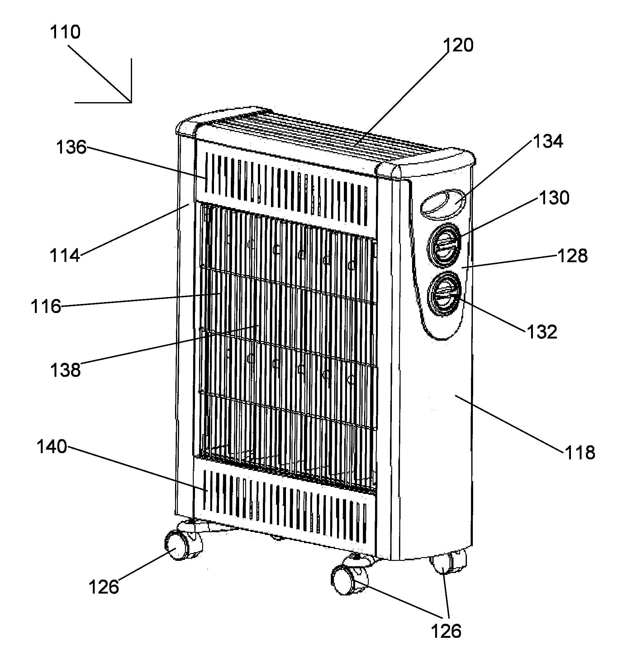
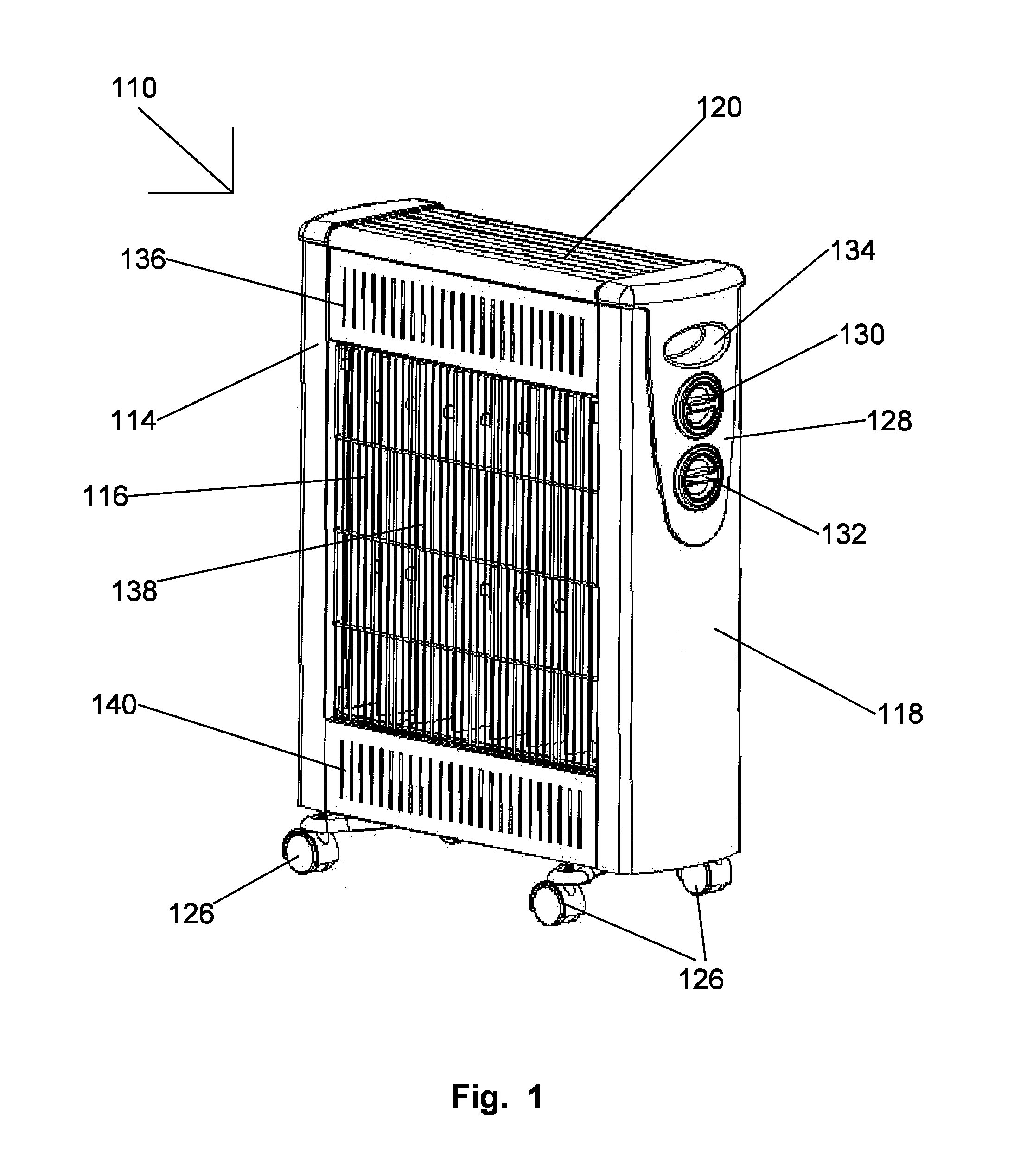
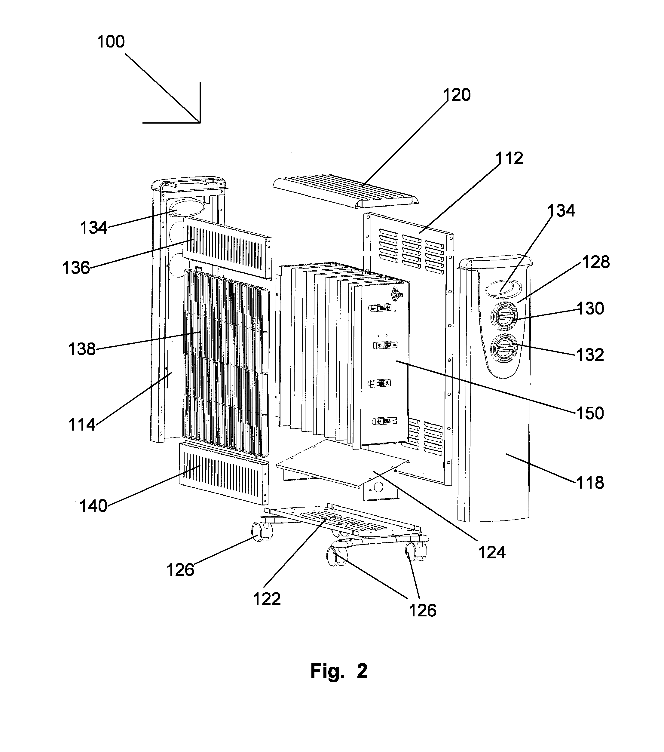
[0071]It is thus one aspect, embodiment, objective and advantage of the present invention to provide a heating core for a heater, said heating core comprising: a corrugated heat conductive fin; a first side panel attached to a first end of said fin; a second side panel attached to a second end of said fin; and at least one heating element mounted to and extending between said first and second side panels; wherein said fin is self-supporting between said first and second side panels.
[0072]It is thus another aspect, embodiment, objective and advantage of the present invention to provide a heating core for a heater, further comprising an additional third panel attached to said first and second side panels, with a space between said additional third panel and said fin.
[0073]It is thus another aspect, embodiment, objective and advantage of the present invention to provide a heating core for a he...
PUM
 Abstract
Description
Claims
Application Information