Pallet for use with lift jack

a technology for lifting jacks and pallets, applied in the field of pallets, can solve the problems of lateral projections slipping off the pallet lifting jack, the recesses do not permit cross-stacking of empty half pallets, and the feet do not fit into the recesses, so as to improve the stability of stacked half pallets, easy repair of damaged pallets, and simple and fast assembly and disassembly

a technology for lifting jacks and pallets, applied in the field of pallets, can solve the problems of lateral projections slipping off the pallet lifting jack, the recesses do not permit cross-stacking of empty half pallets, and the feet do not fit into the recesses, so as to improve the stability of stacked half pallets, easy repair of damaged pallets, and simple and fast assembly and disassembly

US7293509B2Active Publication Date: 2007-11-13REHRIG PACIFIC CO INC

Image

  • Pallet for use with lift jack
  • Pallet for use with lift jack
  • Pallet for use with lift jack

Examples


Embodiment Construction

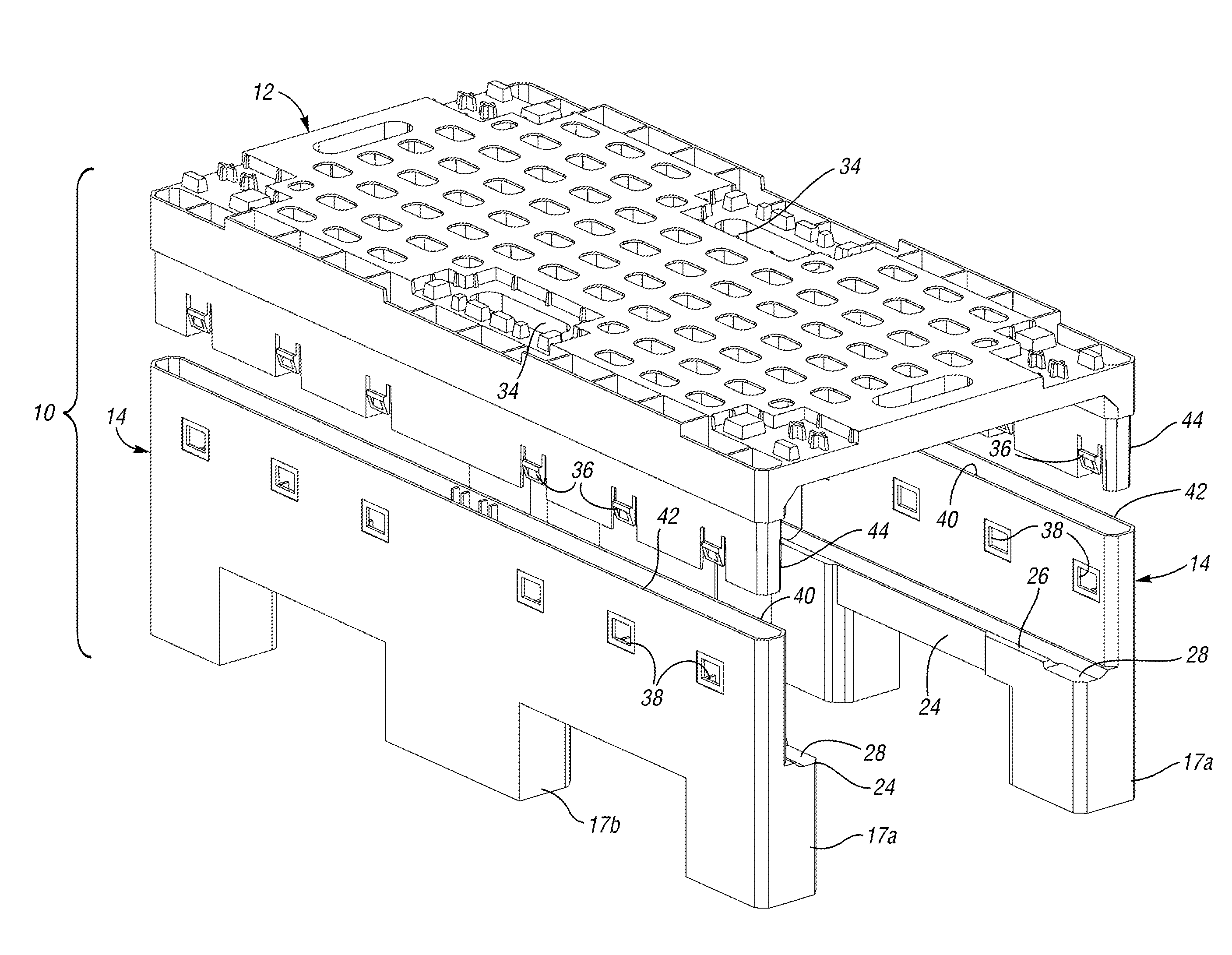
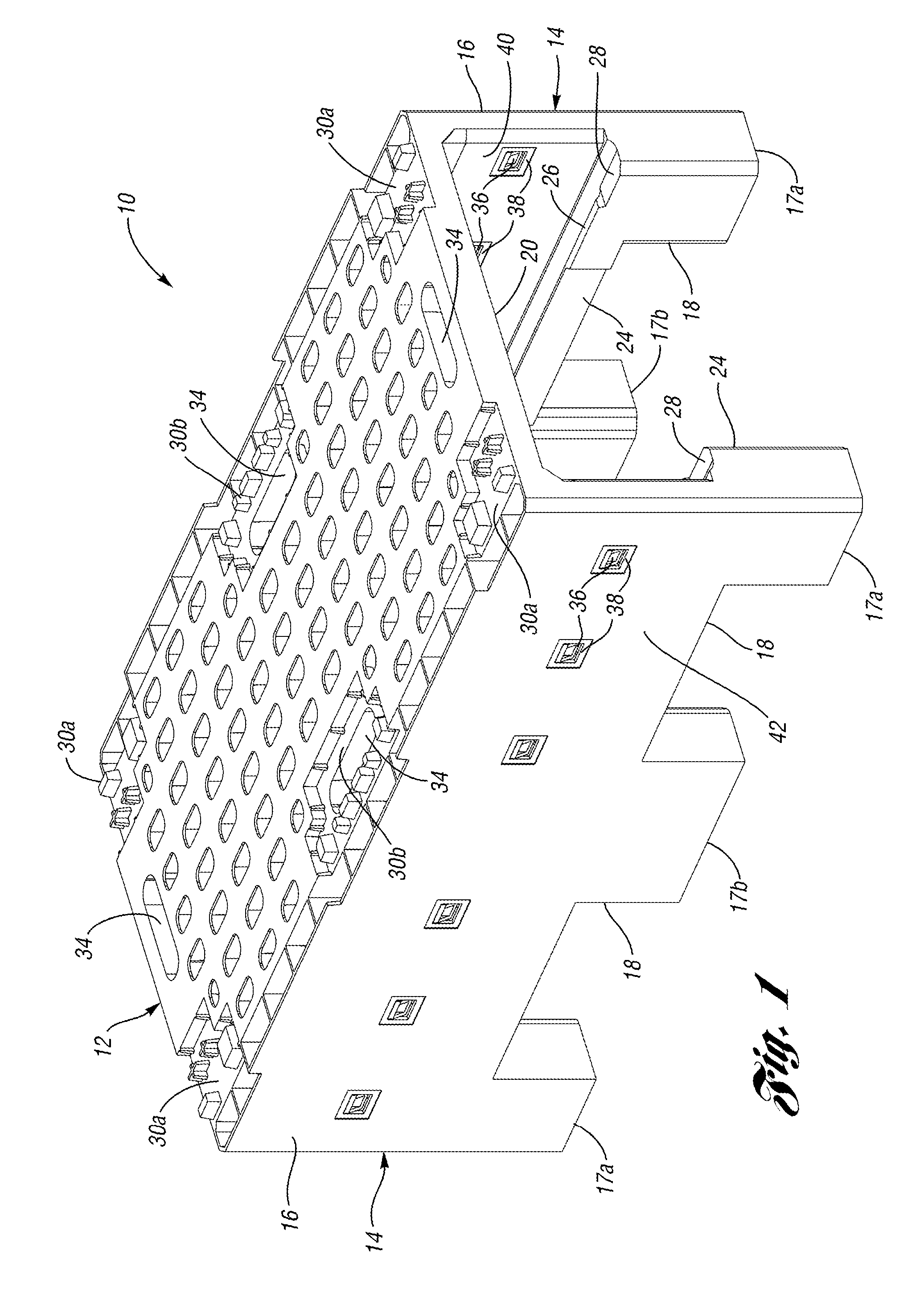
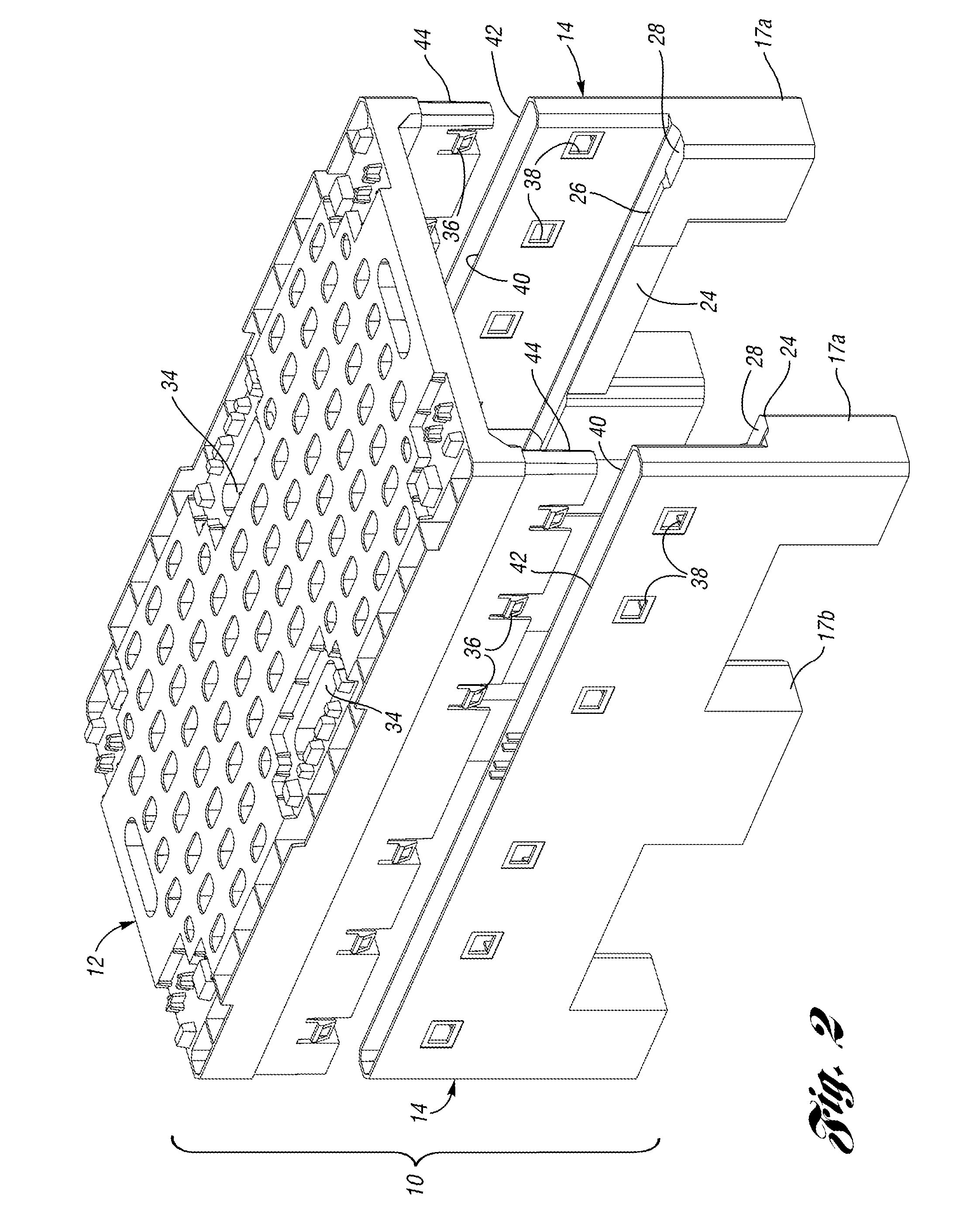
[0021]A pallet 10 of the half-pallet type is shown in FIG. 1. The pallet 10 includes a deck 12 supported by two supports 14. Each support 14 includes a side wall 16 and two corner feet 17a and a side foot 17b (collectively “feet 17”). Side walls 16 extend partially down from the deck 12 and connect the feet 17 to define fork-receiving openings 18. A pallet lift jack opening 20 is defined at each end of the pallet by the deck 12 and supports 14.

[0022]Each of the side walls 14 includes an elongated lateral projection 24 extending inwardly (i.e. toward the opposite support 14). The lateral projection 24 in the embodiment shown extends the entire length of the side wall 14, including the feet 17. Alternatively, the lateral projection 24 could just extend between the feet 17 or only from the feet 17. A vertical projection 26 protrudes upwardly from an inner end of the lateral projection 24. The vertical projection 26 may also extend the entire length of the side wall 14, but in the embod...


PUM


Abstract

A half pallet for use with a pallet lift jack includes a deck that is snap-fit to a plurality of supports. A lateral projection extends inwardly from each of the supports. A vertical projection protrudes upwardly from an inner end of the lateral projection and is spaced from the support such that a portion of a frame of the pallet lift jack can be received between the vertical projection and the support to prevent outward deflection of the supports.

Description

CROSS-REFERENCE TO RELATED APPLICATION[0001]This application is related to U.S. application Ser. No. 11 / 044,741 filed Jan. 26, 2005.BACKGROUND OF THE INVENTION[0002]This invention relates to a pallet. Pallets are often used to store and transport goods. Pallets maintain the goods at a distance above the floor such that they can readily be lifted and moved by a forklift. Plastic pallets are lighter and more durable than wooden pallets.[0003]Some pallets are half the size of standard-sized pallets and are known as “half-pallets.” The half-pallets include a deck and a plurality of spaced-apart feet extending down from the deck to form openings. These half-pallets are transported short distances, such as from a delivery truck into a store, by a person on a wheeled pallet lift jack. The pallet lift jack is first rolled into an opening between the feet of a loaded half-pallet. A pneumatic or mechanical lift mechanism on the pallet lift jack then lifts deck of the half-pallet upward until ...

Claims


Application Information

Patent Timeline
13 Nov 2007
Publication
US7293509B2
IPC
B65D19/12
CPC
B65D19/004; B65D19/18; B65D2519/00756; B65D2519/00034; B65D2519/00069; B65D2519/00104; B65D2519/00174; B65D2519/00288
Inventors
HASSELL, JON P.