Sanding rope and applications thereof

a technology of sanding rope and sanding rod, which is applied in the field of sanding rope, can solve the problems of inconvenient installation or wrapping of a separate piece of sandpaper around the device, the inability to achieve effective use of sandpaper, and the inability to apply firm pressure long enough to complete the job and apply even pressure, etc., and achieves convenient off-the-shelf use, low cost, and sufficient low cost

Inactive Publication Date: 2007-11-20
PONTIERI JAMES M
View PDF24 Cites 5 Cited by
  • Summary
  • Abstract
  • Description
  • Claims
  • Application Information

AI Technical Summary

Benefits of technology

[0013]An object of the present invention is to develop a low cost (and thus disposable) hand held sanding device made of lightweight, resilient material capable of recovering its shape after being subjected to radial or axial pressures attendant its usage as a sanding device. The device has a contoured outer surface which can be deformed to match the small, intricate shapes of furniture balusters, moldings and trim. While shaped molding and trim are specifically identified as possible contoured shapes to which the sanding device of the invention can be applied, it shall be understood that the contoured surface of the device can be applied with almost any sandable surface and material.
[0014]According to the present invention, a disposable hand sanding device includes an elongated, generally rod shaped base portion which is constructed of lightweight resilient material such as closed cell foam or rubber and is formed with a substantially constant cross-section along its characteristic line of elongation. An abrasive outer surface layer is permanently formed on the base portion by adhering abrasive material such as silicon carbide or aluminum oxide upon an intermediate adhesive layer. This arrangement results in a hand held device which, in application, conforms to curvilinear contours of a work piece to be sanded upon application of user induced loading against the workpiece. The device is light weight, easy to use and is extremely inexpensive to manufacture.
[0015]As an additional feature, an elongated, non-resilient flexible cord is embedded within the base portion and extends substantially concentrically with the base portion to limit axial distension of the sanding device upon application of user induced loading. The cord, when exposed, also facilitates manual manipulation of the sanding device.

Problems solved by technology

The difficulty in hand-sanding is in applying firm pressure long enough to complete the job and in applying even pressure to obtain a desired smooth and even finish.
A further difficulty is to obtain efficient use of the sandpaper by not wasting any substantial portion of its surface area.
The difficulty with the above-mentioned prior sanding devices is the necessity of installing or wrapping a separate piece of sandpaper around the device.
This installation or wrapping process presents some inconvenience to the user, and the paper, if improperly installed, is susceptible to falling off.
Also, the device requires the purchase of separate sheets of sandpaper which is a further inconvenience in terms of the amount of supplies needed.
Thirdly, when a sanding block having a flat sanding paper supporting surface is used to sand a flat surface, the block reduces points of excessive pressure by more evenly distributing the user's force over the sandpaper supporting surface.
However, when non-flat surfaces need to be sanded, difficulties often arise.
The standard sanding block has a relatively large, flat sandpaper supporting surface which does not satisfactorily meet the needs of one who is sanding an irregular surface.
The use of such a sanding block on an irregular surface will generally result in the user angling the block or using it in a way in which it was not intended in an attempt to conform the sanding surface to the work surface.
Even with such attempts, the resultant effect is uneven sanding as generally no portion of the block will conform exactly to the area being sanded and excessive areas of pressure which will result in over sanding.
Excessive pressure points can also result in the quickened wearing of the sandpaper, such that the sanding block itself may become exposed, which, depending upon the fabrication of the sanding block, may damage the work surface.
Similarly, as the user angles the sanding block in order to utilize a corner or edge of the sandpaper, a portion of the block not covered by the sandpaper may scratch the work surface.
While such devices may be suitable for their intended uses, they do not sufficiently meet the myriad surface irregularities often encountered when sanding a complex work piece.
It should be easily appreciated that these later approaches, while at times effective, are not reasonable alternatives when extreme precision or small detailed contours, such as in furniture finishing, are involved.

Method used


Image

  • Sanding rope and applications thereof
  • Sanding rope and applications thereof
  • Sanding rope and applications thereof

Examples


Embodiment Construction

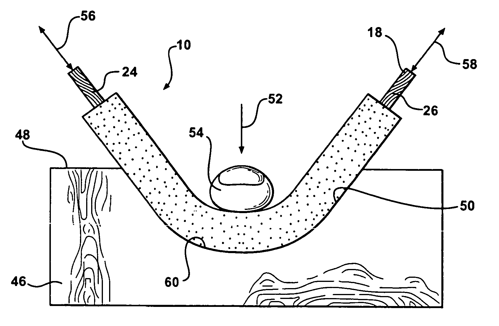
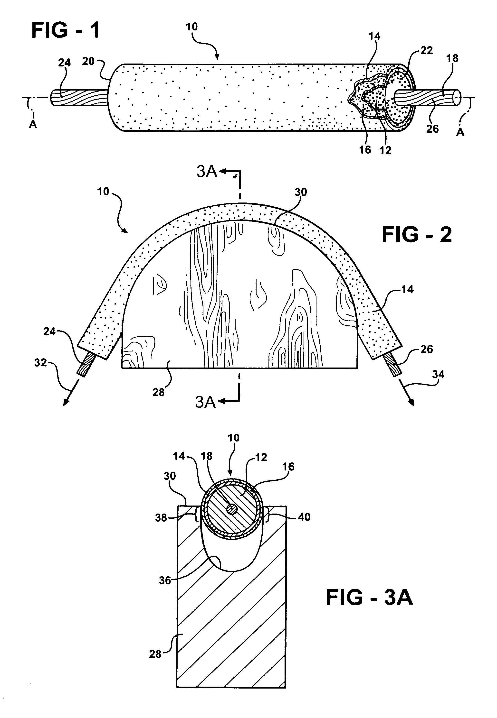
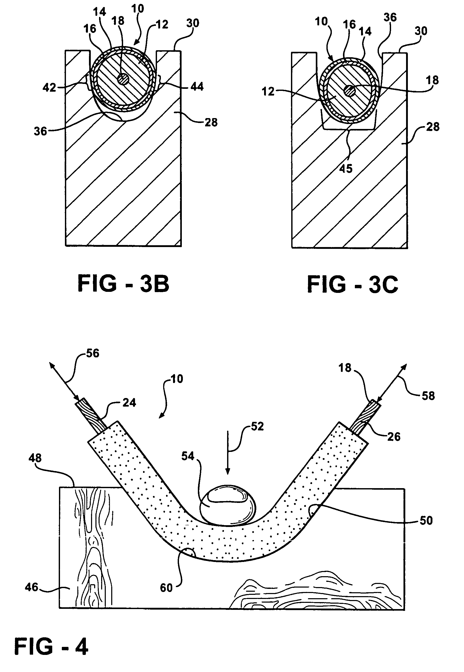
[0047]FIG. 1 illustrates a preferred embodiment of the present invention. A disposable sanding rope or device 10 is formed as a generally rod shaped base portion 12 elongated along an axis designated A-A. Base portion 12 is preferably formed from lightweight resilient material such as closed cell foam or rubber. It is contemplated that many other suitable materials such as urethane or neoprene could be substituted, however, based upon an understanding of the present invention and a given specific application.

[0048]The outer circumferential surface of base portion 12 is substantially covered with an abrasive coating layer 11 suitably affixed to the underlying base portion 12 by an intermediate adhesive layer 16. Adhesive layer 16 is spray applied to base portion 12 prior to application of a suitable aggregate abrasive 14 such as coarse aluminum oxide or silicon carbide. Such materials are commercially available from the Household and Hardware Products Division of the 3M Company under...


PUM


Abstract

A disposable sanding device is fabricated as a continuous rope-like article which is adapted for selective segmentation and application as a plurality of serially arranged disposable hand sanding devices or ropes. Each hand sanding device is formed as a generally elongated rod shaped base portion formed of lightweight material such as closed cellfoam having a relatively constant cross-section along its line of elongation. An abrasive surface is permanently applied to the external surface of the base portion via an intermediate adhesive layer. As constructed, the sanding device is operable to conform to curvilinear contours of a work piece to be sanded upon application of user induced loading against the work piece. A dispenser holds a rolled length of sanding rope and includes a cutter feature for severing pieces of sanding rope from the coil as required as well as a retainer for the free end of the coil. A tensioning hand tool holds a severed length of sanding rope for precise applications. Interconnection means is provided to concentrically position and affix opposed ends of a base portion segment.

Description

RELATED PATENT APPLICATION[0001]This application is a divisional an application entitled “Sanding Rope and Applications Thereof”, U.S. Ser. No. 11 / 133,529, filed 20 May 2005, now U.S. Pat. No. 7,144,314 B2, issued 5 Dec. 2006, which is a continuation-in-part of a parent application entitled “Sanding Rope and Method of Forming Same”, U.S. Ser. No. 10 / 860,694, filed 3 Jun. 2004, now U.S. Pat. No. 6,997,794 B2, issued 14 Feb. 2006, and owned by the common inventor / applicant.[0002]The present invention relates generally to hand tools and particularly to sanding devices, especially for use in wood working. More particularly still, the present invention relates to a low cost, hand-held disposable sanding device which can be easily manipulated by hand for sanding and finishing a wide variety of work piece surface shapes and configurations.BACKGROUND OF THE INVENTION[0003]Small sanding jobs and sanding jobs calling for considerable detail work or access to small confined areas will usually ...

Claims


Application Information

Patent Timeline
Patent Type & Authority Patents(United States)
IPC IPC(8): B24D15/00B24D99/00B24B9/10B24D15/04
CPCB23D61/185B24D11/06B24D99/00B24D15/04Y10S451/913
Inventor PONTIERI, JAMES M.
Owner PONTIERI JAMES M
Why Eureka
Try Eureka