Motion vector derivation method, dynamic image encoding method, and dynamic image decoding method

a dynamic image and vector technology, applied in the field of motion vector derivation method, dynamic image encoding method, dynamic image decoding method, can solve the problems of large memory capacity and more calculation time for division, and achieve the effect of simplifying the derivation of motion vectors

Active Publication Date: 2008-02-05
PANASONIC INTELLECTUAL PROPERTY CORP OF AMERICA
View PDF7 Cites 37 Cited by
  • Summary
  • Abstract
  • Description
  • Claims
  • Application Information

AI Technical Summary

Benefits of technology

[0018]Accordingly, multiplication can be performed instead of division required for scaling a reference motion vector. Also, since a value of a parameter used for scaling a reference motion vector is limited to a predetermined range, data amount on a multiplier parameter table stored in a memory can be reduced. In addition, inconsistency in the results due to calculation error between coding and decoding can be prevented.

Problems solved by technology

However, since digitalized images have an enormous amount of data, information compression techniques are of absolute necessity for their storage and transmission.
However, as the first problem, division takes more time for calculation than calculation such as addition and multiplication.
However, as the second problem, since various values are applied to parameters for deriving motion vectors depending on distances between reference pictures and a picture including a current block, the parameters can have a wide range of values.
An enormous number of parameters must be prepared for multiplier parameters corresponding to all the divisors, and thus large memory capacity is required.

Method used


Image

  • Motion vector derivation method, dynamic image encoding method, and dynamic image decoding method
  • Motion vector derivation method, dynamic image encoding method, and dynamic image decoding method
  • Motion vector derivation method, dynamic image encoding method, and dynamic image decoding method

Examples


first embodiment

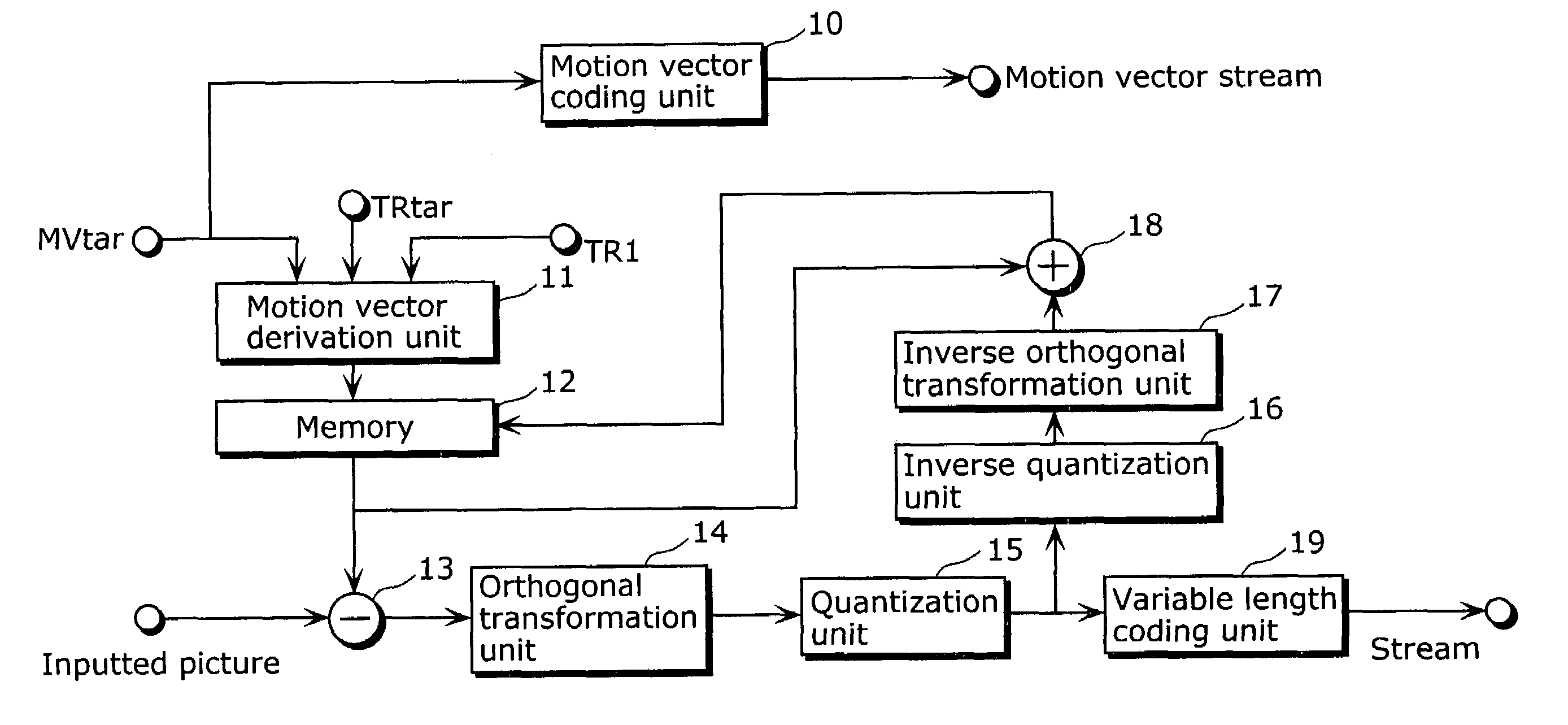
[0044]FIG. 3 is a block diagram showing a structure of a moving picture coding apparatus according to the first embodiment. In FIG. 3, the terms which have already been explained in the background art with reference to FIG. 1 will be explained using the same signs as those in FIG. 1. The present embodiment is different from the conventional art in that parameters used for deriving motion vectors of the current picture to be coded 1202 are limited to a predetermined range of values.

[0045]As shown in FIG. 3, the moving picture coding apparatus includes a motion vector coding unit10, a motion vector derivation unit 11, a memory 12, a subtracter 13, an orthogonal transformation unit 14, a quantization unit 15, an inverse quantization unit 16, an inverse orthogonal transformation unit 17, an adder 18 and a variable length coding unit 19.

[0046]The motion vector coding unit 10 encodes motion vectors (such as MV1) of respective pictures for output as a motion vector stream. The motion vecto...

second embodiment

[0077]In the above first embodiment, when a motion vector MVtar that is a reference motion vector is scaled to derive motion vectors MVscl, a parameter TR1 is compared with the upper limit of divisors stored in a multiplier parameter table, and if TR1 is the upper limit or larger, a value corresponding to the maximum divisor in the multiplier parameter table is used as a multiplier parameter corresponding to the inputted parameter TR1. In the second embodiment, the parameter TR1 is compared with the upper limit of divisors stored in the multiplier parameter table, and if TR1 is the upper limit or larger, the inputted MVtar is used as it is as the motion vectors MVscl without scaling the motion vector MVtar, and thus derivation of the motion vectors MVscl can be simplified when TR1 is the upper limit or larger. The second embodiment of the present invention will be explained below with reference to figures.

[0078]FIG. 8 is a block diagram showing a structure of a motion vector derivat...

third embodiment

[0103]FIG. 13 is a block diagram showing a structure of a moving picture decoding apparatus according to the third embodiment.

[0104]As shown in FIG. 13, the moving picture decoding apparatus includes a variable length decoding unit1000, an inverse quantization unit 1001, an inverse orthogonal transformation unit 1002, an addition unit 1003, a motion vector decoding unit 1004, a motion vector derivation unit 1005 and a memory 1006. Note that the specific explanation of the structure and operation of the motion vector derivation unit 1005 will be omitted because they are same as those of the first and second embodiments.

[0105]The variable length decoding unit 1000 performs variable length decoding for the coded data stream outputted from the moving picture coding apparatus according to each of the above embodiments, and outputs coded prediction error data to the inverse quantization unit 100, and outputs at the same time motion vector derivation parameters TRtar and TR1 to the motion ...


PUM


Abstract

A motion vector derivation unit (11) includes a comparison unit (20) for comparing a parameter TR1 for a reference vector with a predetermined value to determine whether it exceeds the predetermined value or not; a switching unit (21) for switching selection between the maximum value of a pre-stored parameter TR and the parameter TR1 according to the comparison result by the comparison unit (20); a multiplier parameter table (for multipliers) (22); and a multiplier parameter table (for divisors) (24) for associating the parameter TR1 with a value approximate to the inverse value (1 / TR1) of this parameter TR1.

Description

TECHNICAL FIELD[0001]The present invention relates to a motion vector derivation method for deriving a motion vector indicating motion of each block between pictures, a moving picture coding method for coding a moving picture by inter picture prediction coding involving motion compensation using the derived motion vector, and a moving picture decoding method.BACKGROUND ART[0002]With the development of multimedia applications, it has become common in recent years to handle information of all sorts of media such as audio, video and text in an integrated manner. In doing so, it becomes possible to handle media integrally by digitalizing all the media. However, since digitalized images have an enormous amount of data, information compression techniques are of absolute necessity for their storage and transmission. On the other hand, in order to interoperate compressed image data, standardization of compression techniques is also important. Standards on image compression techniques includ...

Claims


Application Information

Patent Timeline
Patent Type & Authority Patents(United States)
IPC IPC(8): H04B1/66H04N7/12A01N47/12A01N37/42A01P3/00G06F1/03H04N7/26H04N7/32H04N7/36H04N7/46H04N7/50
CPCG06F1/03H04N19/00781H04N21/2743H04N19/52H04N19/503H04N19/51H04N19/61H04N19/43H04N19/577H04N19/00696H04N19/00587H04N19/00575H04N19/00509H04N19/00733H04N19/00721G06F2101/12H04N19/105H04N19/124H04N19/172H04N19/176H04N19/30H04N19/513H04N19/587H04N19/625
Inventor KADONO, SHINYAKONDO, SATOSHIHAGAI, MAKOTOABE, KIYOFUMI
Owner PANASONIC INTELLECTUAL PROPERTY CORP OF AMERICA
Why Eureka
Try Eureka