Lamp with inner lamp-stem assembly and method for manufacture

a technology of inner lamp stem and lamp body, which is applied in the manufacture of electrode systems, electric discharge tubes/lamps, light and heating apparatus, etc., can solve the problems of increased production cost, increased production cost, and inconvenient assembly of inner lamp stems, so as to facilitate direct pinching and reduce overall length of inner lamp stem assembly , the effect of compact siz

a technology of inner lamp stem and lamp body, which is applied in the manufacture of electrode systems, electric discharge tubes/lamps, light and heating apparatus, etc., can solve the problems of increased production cost, increased production cost, and inconvenient assembly of inner lamp stems, so as to facilitate direct pinching and reduce overall length of inner lamp stem assembly , the effect of compact siz

US7329993B2Inactive Publication Date: 2008-02-12GENERAL ELECTRIC CO

Image

  • Lamp with inner lamp-stem assembly and method for manufacture
  • Lamp with inner lamp-stem assembly and method for manufacture
  • Lamp with inner lamp-stem assembly and method for manufacture

Examples


Embodiment Construction

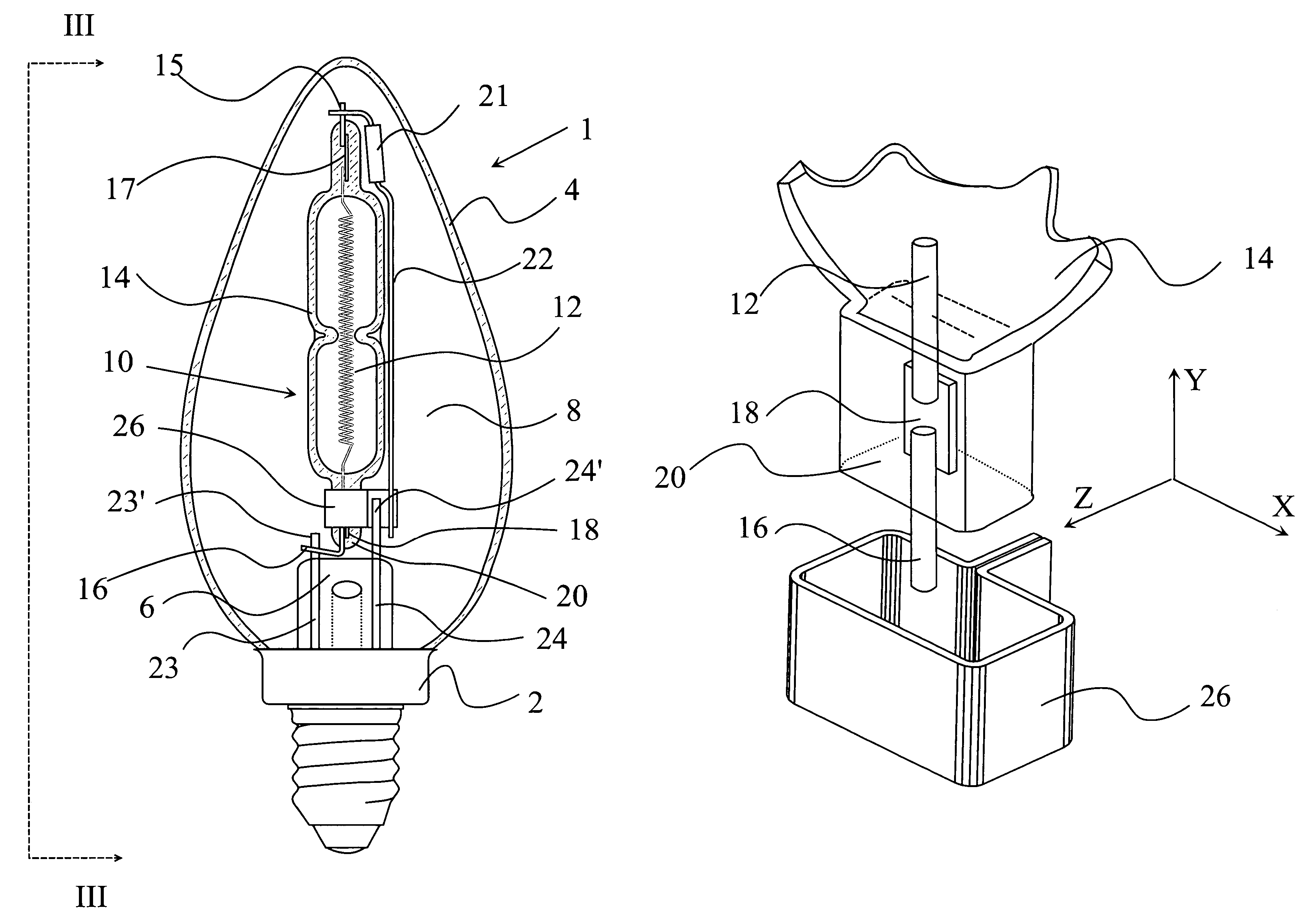
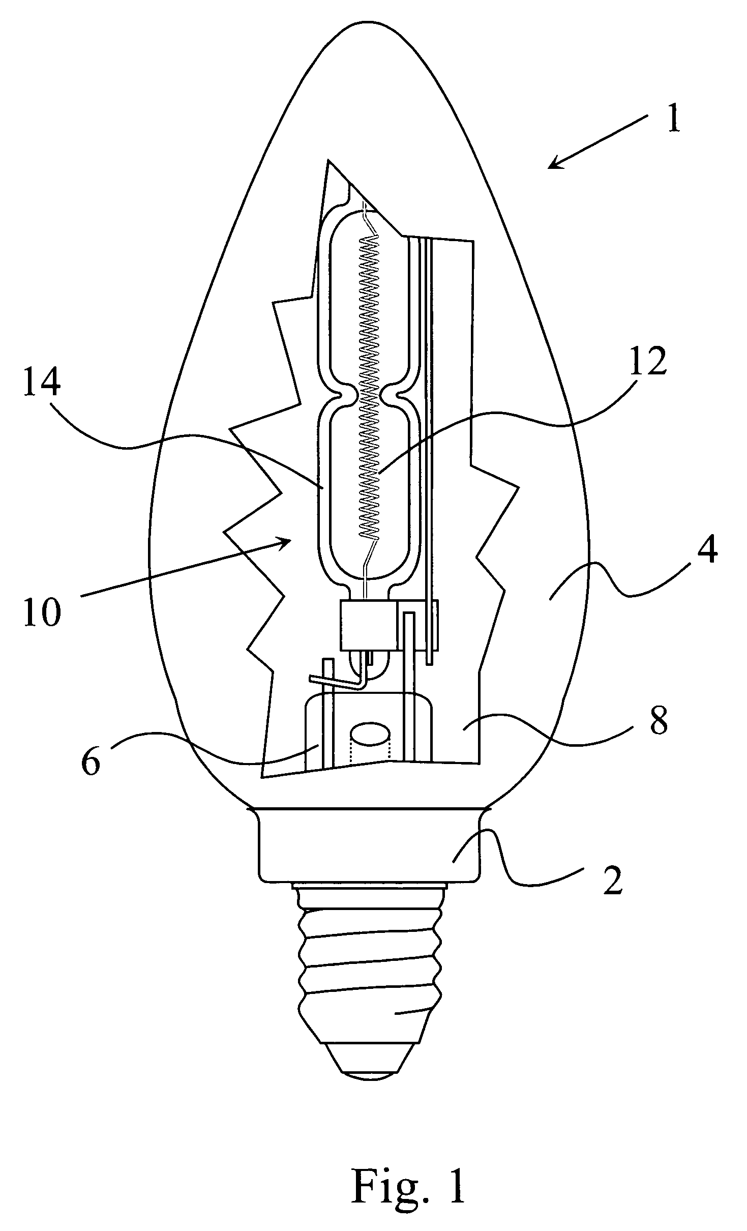
[0018]Referring now to FIGS. 1 to 3, there is shown a lamp 1 in the form of a standard household lamp, in the shown embodiment a candle lamp according to the standard B 35. The lamp 1 is equipped with a lamp base 2 and a translucent outer envelope 4. The lamp base 2 is connected to a stem 6 and the outer envelope 4. Though not shown in detail, the stem 6 and the outer envelope 4 are sealed in a region covered by the lamp base 2, hermetically sealing an inner volume 8 surrounded by the outer envelope 4. A halogen inner lamp 10 functions as the actual light source within the lamp 1. This halogen inner lamp 10 contains a filament 12 in a halogen gas atmosphere, which latter is sealed within an inner lamp jacket 14. The filament 12 is connected to inner leads 15, 16 through conductor foils 17, 18 (see also FIG. 4). These conductor foils 17, 18 are acting as the sealed lead-through conductors. The material of the foil is mostly molybdenum. The conductor foils 17, 18 are embedded in pinch...


PUM


Abstract

A lamp includes a lamp base with a stem having two leads. Free portions of the leads extend from the stem substantially parallel to each other and define a first plane. The lamp further includes a translucent outer envelope and a halogen inner lamp light source having a pinched end. The pinched end defines a second plane, and it is located in the vicinity of the stem. The first plane defined by the free portions of the leads is substantially perpendicular to the second plane defined by the pinched end.

Description

BACKGROUND OF THE INVENTION[0001]This invention relates to a lamp comprising a halogen inner lamp that is attached to a stem in the lamp.[0002]Ordinary household lamps with an incandescent filament have been known for a long time. These lamps comprise a filament enclosed in a glass envelope or jacket. These lamps, while relatively cheap and reliable, are not energy-efficient. Compact fluorescent lamps have a higher efficiency, but they are more expensive, while many people perceive their spectrum as less natural. Therefore, it has been proposed to incorporate into a traditional glass bulb a smaller halogen light source, in the form of an inner lamp, having its own envelope and filament. Such inner lamps can be more efficient, because it is easier to maintain the ideal conditions for the heating of a filament within a small volume, surrounded by a relatively thick, and therefore strong envelope. Since it is a major objective to produce these lamps in a cost-effective manner, it is so...

Claims


Application Information

Patent Timeline
12 Feb 2008
Publication
US7329993B2
IPC
H01J61/33; F21V19/00; H01K1/40; H01J5/54; H01J5/62; H01J9/36; H01J17/16; H01J61/30; H01J61/34; H01J61/36; H01J61/82; H01K1/00; H01K1/34; H01K3/00; H01K3/08; H01K3/12
CPC
H01J5/54; H01J5/62; H01J61/34; H01J61/368
Inventors
FULOP, GABOR