Disk brake

a technology of brakes and disks, applied in the direction of brakes, cycle brakes, floor carpets, etc., to achieve the effect of preventing the generation of sounds

Inactive Publication Date: 2008-02-26
HONDA MOTOR CO LTD
View PDF22 Cites 5 Cited by
  • Summary
  • Abstract
  • Description
  • Claims
  • Application Information

AI Technical Summary

Benefits of technology

[0007]The present invention has been made in consideration of the above circumstances. Accordingly, it is an object of the present invention to provide a disk brake so configured as to restrain at least movements of a retainer relative to a support portion of a bracket, thereby preventing generation of sounds.
[0012]According to the first aspect of the invention, at least the retainer supporting force for supporting the retainer on the support portion is set to be not less than the received force exerted on the friction pad due to vibration. Therefore, against the received force exerted on the friction pad owing to vibration exerted on the friction pad or the like, the retainer can be supported so as not to move relative to the support portion of the bracket, whereby at least movements of the retainer relative to the support portion of the bracket can be restrained, and generation of sounds can be prevented.
[0013]In addition, according to the second aspect of invention, the pad holding force with which the retainer holds the friction pad is also set to be not less than the received force on the friction pad. Therefore, it is possible not only to restrain movements of the retainer relative to the support portion of the bracket but also to restrain relative movements of the friction pad and the retainer, whereby generation of sounds can be prevented more effectively. Moreover, since the pad holding force with which the friction pad is held by the retainer is not set to be irrationally large, optimum designing of the retainer can be carried out speedily.
[0014]According to the third aspect of the invention, even though a part of the disk brake is disposed in the opening portion of the swing arm where resonance of sounds is liable to occur, generation of sounds can be restrained, so that the degree of freedom in laying out the disk brake relative to the swing arm can be enhanced.
[0015]Furthermore, according to the fourth aspect of the invention, the retainer supporting force for supporting the retainer on the support portion can be easily set to be not less than the received force exerted on the friction pad from the brake disk.

Problems solved by technology

However, if the retainer is moved relative to the support portion of the bracket when a vibration is exerted on the friction pad, the retainer may collide on the support portion to generate a sound, and there is no disclosure in Japanese Patent Laid-open No.

Method used


Image

  • Disk brake
  • Disk brake
  • Disk brake

Examples


Embodiment Construction

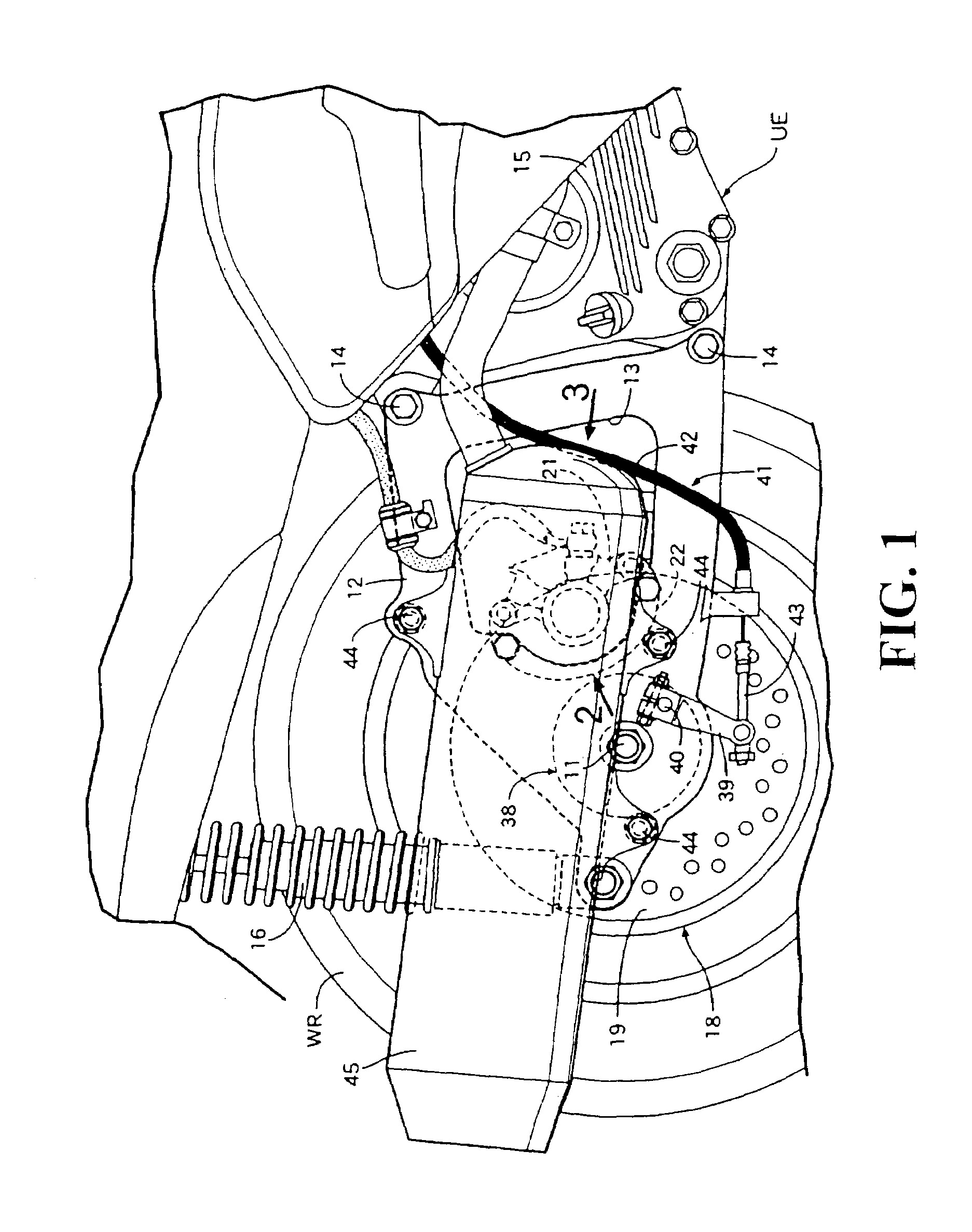
[0026]First, in FIG. 1, a unit swing engine UE for producing power for driving a rear wheel WR is vertically swingably mounted on the motor scooter type vehicle, with its rear portion disposed on the left side of the rear wheel WR, and an axle 11 of the rear wheel WR is rotatably supported between a rear portion of a swing arm 12, which is connected to the unit swing engine UE and is disposed on the right side of the rear wheel WR, and a rear portion of the unit swing engine UE.

[0027]The swing arm 12 is provided in a roughly central portion thereof with an opening portion 13 so formed that its vertical width decreases toward the rear side, and the swing arm 12 is so formed that its side view is a roughly triangular shape narrowed on the rear end side. Upper and lower two portions in a front portion of the swing arm 12 are fastened to a crankcase 15 possessed by the unit swing engine UE by bolts 14, 14, and the lower end of a rear cushion 16 is connected to the rear end of the swing ...


PUM


Abstract

A disk brake including friction pads disposed opposite to a brake disk, a bracket provided with support portions for movably supporting the friction pads so as to permit sliding along the axial direction of the brake disk, and retainers each interposed between the friction pad and the support portions, to restrain at least movements of the retainers relative to the support portions of the bracket. Of a pad holding force with which the retainer holds the friction pad, and a retainer supporting force for supporting the retainer on the support portion, at least the retainer supporting force is set to be not less than a received force exerted on the friction pad due to vibration. The resulting configuration prevents generation of rattling sounds due to the vibration.

Description

CROSS-REFERENCE TO RELATED APPLICATION[0001]The present application claims priority under 35 U.S.C. § 119 to Japanese Patent Application No. 2004-063115, filed Mar. 5, 2004, the entire contents of which are hereby incorporated by reference.BACKGROUND OF THE INVENTION[0002]1. Field of the Invention[0003]The present invention relates to a disk brake including friction pads disposed opposite to a brake disk, a bracket provided with support portions for movably supporting the friction pad so as to permit sliding along the axial direction of the brake disk, and retainers each interposed between the friction pad and the support portion.[0004]2. Description of Background Art[0005]A disk brake in which retainers are interposed between both ends of a friction pad along the circumferential direction of a brake disk and support portions provided on a bracket is disclosed, for example, in Japanese Patent Laid-open No. Hei 10-122278. In this disk brake, the friction pad is springily held by the ...

Claims


Application Information

Patent Timeline
Patent Type & Authority Patents(United States)
IPC IPC(8): F16D65/40B62K25/28B62L1/00F16D55/2265F16D55/227F16D65/097
CPCB62L1/00F16D65/0978F16D65/0972F16D55/227A47G27/0212
Inventor NAKAIE, HIROKATSUHONDA, YOSHINOBU
Owner HONDA MOTOR CO LTD
Why Eureka
Try Eureka