Method of manufacturing of a diffraction grating-based optical identification element

a technology of optical identification elements and manufacturing methods, which is applied in the field of identification elements, can solve the problems of insufficient fluorescence and other optical techniques, insufficient different codes, and inability to withstand harsh temperature, chemical, nuclear and/or electromagnetic environments,

Inactive Publication Date: 2008-05-20
CYVERA CORP
View PDF421 Cites 26 Cited by
  • Summary
  • Abstract
  • Description
  • Claims
  • Application Information

AI Technical Summary

Problems solved by technology

Existing technologies, such as bar codes, electronic microchips / transponders, radio-frequency identification (RFID), and fluorescence and other optical techniques, are often inadequate.
For example, existing technologies may be too large for certain applications, may not provide enough different codes, or cannot withstand harsh temperature, chemical, nuclear and / or electromagnetic environments.

Method used


Image

  • Method of manufacturing of a diffraction grating-based optical identification element
  • Method of manufacturing of a diffraction grating-based optical identification element
  • Method of manufacturing of a diffraction grating-based optical identification element

Examples


Embodiment Construction

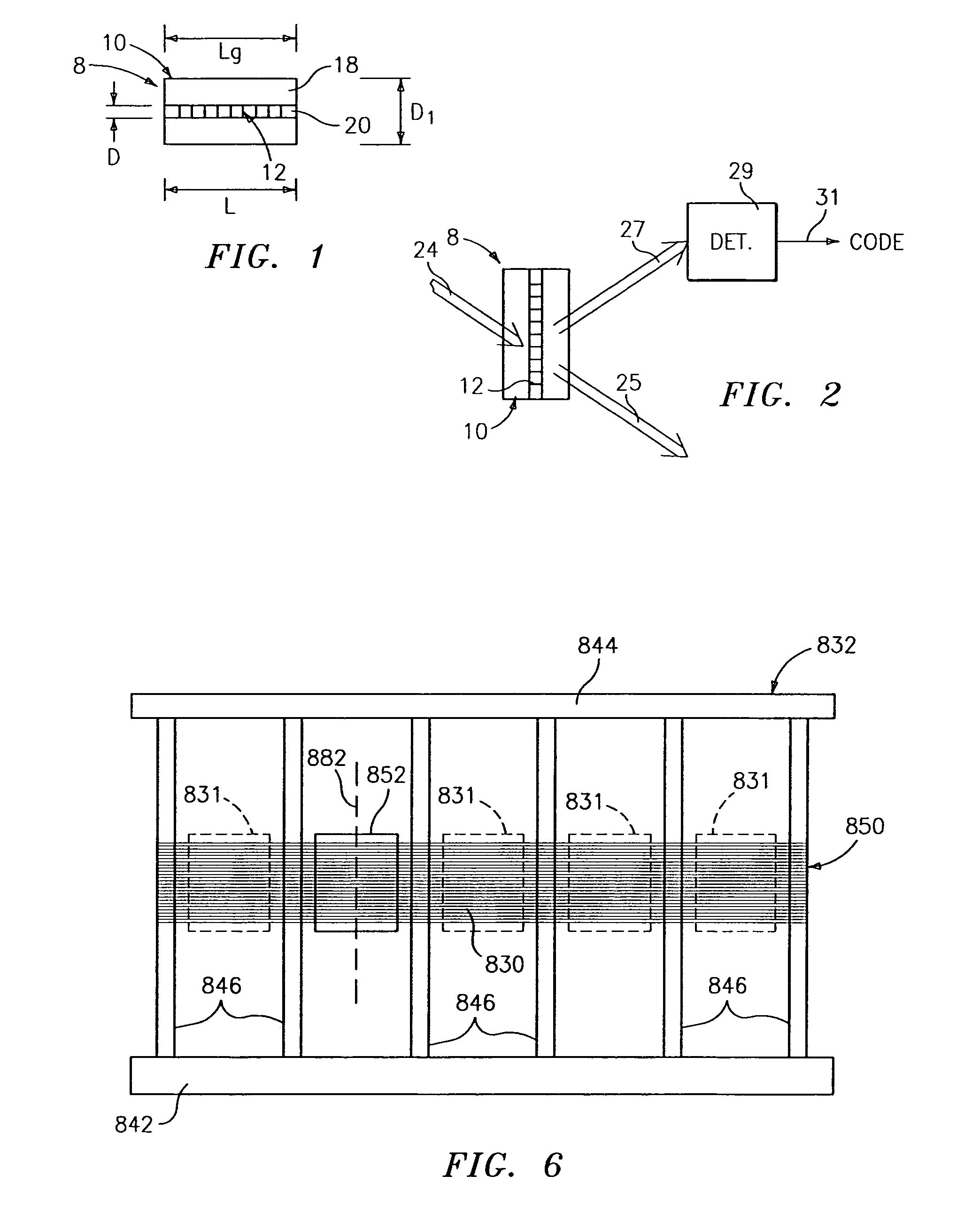
[0061]Referring to FIG. 1, a diffraction grating-based optical identification element 8 (or encoded element or coded element) comprises a known optical substrate 10, having an optical diffraction grating 12 disposed (or written, impressed, embedded, imprinted, etched, grown, deposited or otherwise formed) in the volume of or on a surface of a substrate 10. The grating 12 is a periodic or aperiodic variation in the effective refractive index and / or effective optical absorption of at least a portion of the substrate 10.

[0062]The optical identification element 8 described herein is the same as that described in Copending patent application Ser. No. 10 / 661,234, filed contemporaneously with the parent application, which is incorporated herein by reference in its entirety.

[0063]In particular, the substrate 10 has an inner region 20 where the grating 12 is located. The inner region 20 may be photosensitive to allow the writing or impressing of the grating 12. The substrate 10 has an outer ...


PUM

PropertyMeasurementUnit
blaze angleaaaaaaaaaa
lengthaaaaaaaaaa
angleaaaaaaaaaa

Abstract

A method of manufacturing optical identification elements that includes forming a diffraction grating in a fiber substrate along a longitudinal axis of the substrate. The grating includes a resultant refractive index variation. The method also includes cutting the substrate transversely to form a plurality of optical identification elements that have the grating therein along substantially the entire length of the elements. Each of the elements has substantially the same resultant refractive index variation.

Description

CROSS REFERENCES TO RELATED APPLICATIONS[0001]This application is a continuation of and claims benefit to U.S. patent application Ser. No. 10 / 661,116, filed on Sep. 12, 2003 now U.S. Pat. No. 7,092,160, and claims benefit to U.S. Provisional Patent Application No. 60 / 410,541, filed on Sep. 12, 2002, all of which are incorporated by reference in their entirety.[0002]U.S. patent application Ser. No. 10 / 661,234 and application Ser. No. 10 / 661,082, were filed contemporaneously with the parent application, contains subject matter related to that disclosed herein, which is incorporated by reference in its entirety.TECHNICAL FIELD[0003]This invention relates to identification elements, and more particularly to method of manufacturing diffraction grating based optical identification elements.BACKGROUND ART[0004]Many industries have a need for uniquely identifiable objects or for the ability to uniquely identify objects, for sorting, tracking, and / or identification / tagging. Existing technolo...

Claims


Application Information

Patent Timeline
Patent Type & Authority Patents(United States)
IPC IPC(8): G02B5/18B01J19/00B01L3/00G01N15/14G01N33/52G02B6/34G03H1/00G06T5/00G06V30/224
CPCB01L3/502707B01L3/5085G03H1/0272G06K19/06009B01J2219/00459B01J2219/00463B01J2219/0047B01J2219/005B01J2219/00547B01J2219/00576B01J2219/00702B01L2200/0636B01L2200/0668B01L2300/0654B01L2400/0409B01L2400/0457B01L2400/0487G02B6/02076G03H2210/53G03H2230/10G03H2270/20G03H2270/24Y10S359/90
Inventor PUTNAM, MARTIN A.MOON, JOHNSZCZEPANEK, PAUL S.LI, TUORAUSEO, ANTHONYTRAYNOR, JOSEPH
Owner CYVERA CORP
Why Eureka
Try Eureka