Progressing cavity stator including at least one cast longitudinal section

a technology of stator and longitudinal section, which is applied in the direction of machines/engines, rotary/oscillating piston pump components, liquid fuel engines, etc., can solve the problems of worn or damaged stator sections being replaced in the field at considerable time and expens

Inactive Publication Date: 2008-07-08
SMITH INT INC
View PDF16 Cites 66 Cited by
  • Summary
  • Abstract
  • Description
  • Claims
  • Application Information

AI Technical Summary

Benefits of technology

[0010]Exemplary embodiments of the present invention advantageously provide several technical advantages. For example, exemplary embodiments of this invention include a rigid stator having high torque output. Moreover, exemplary embodiments of this invention are relatively simple and inexpensive to manufacture as compared to prior art rigid stators. Various embodiments of this invention may also promote field service flexibility. For example, worn or damaged stator sections may be replaced in the field at considerable savings of time and expense. Alternatively, stator sections may be replaced, for example, to optimize power section performance (e.g., with respect to speed and power).
[0012]In another aspect, this invention includes a progressive cavity stator. The stator includes an outer stator tube having a longitudinal axis and a helical cavity component deployed substantially coaxially in the stator tube. The helical cavity component includes first and second longitudinal portions. The first longitudinal portion includes at least one rigid longitudinal stator section deployed in the stator tube, the at least one stator section retained by and secured in the stator tube to substantially prevent rotation of the at least one stator section about the longitudinal axis relative to the stator tube. The at least one stator section reinforces an elastomer liner, which is deployed on an internal helical surface of the at least one stator section. The second portion of the helical cavity component includes an elastomer layer deployed in and retained by the stator tube. The elastomer liner in the first portion is substantially continuous with the elastomer layer in the second portion such that the helical cavity component provides an internal helical cavity and such that the helical cavity component includes a plurality of lobes, each of which extends in a substantially continuous helix from one longitudinal end of the stator to another longitudinal end of the stator.

Problems solved by technology

For example, worn or damaged stator sections may be replaced in the field at considerable savings of time and expense.

Method used


Image

  • Progressing cavity stator including at least one cast longitudinal section
  • Progressing cavity stator including at least one cast longitudinal section
  • Progressing cavity stator including at least one cast longitudinal section

Examples


Embodiment Construction

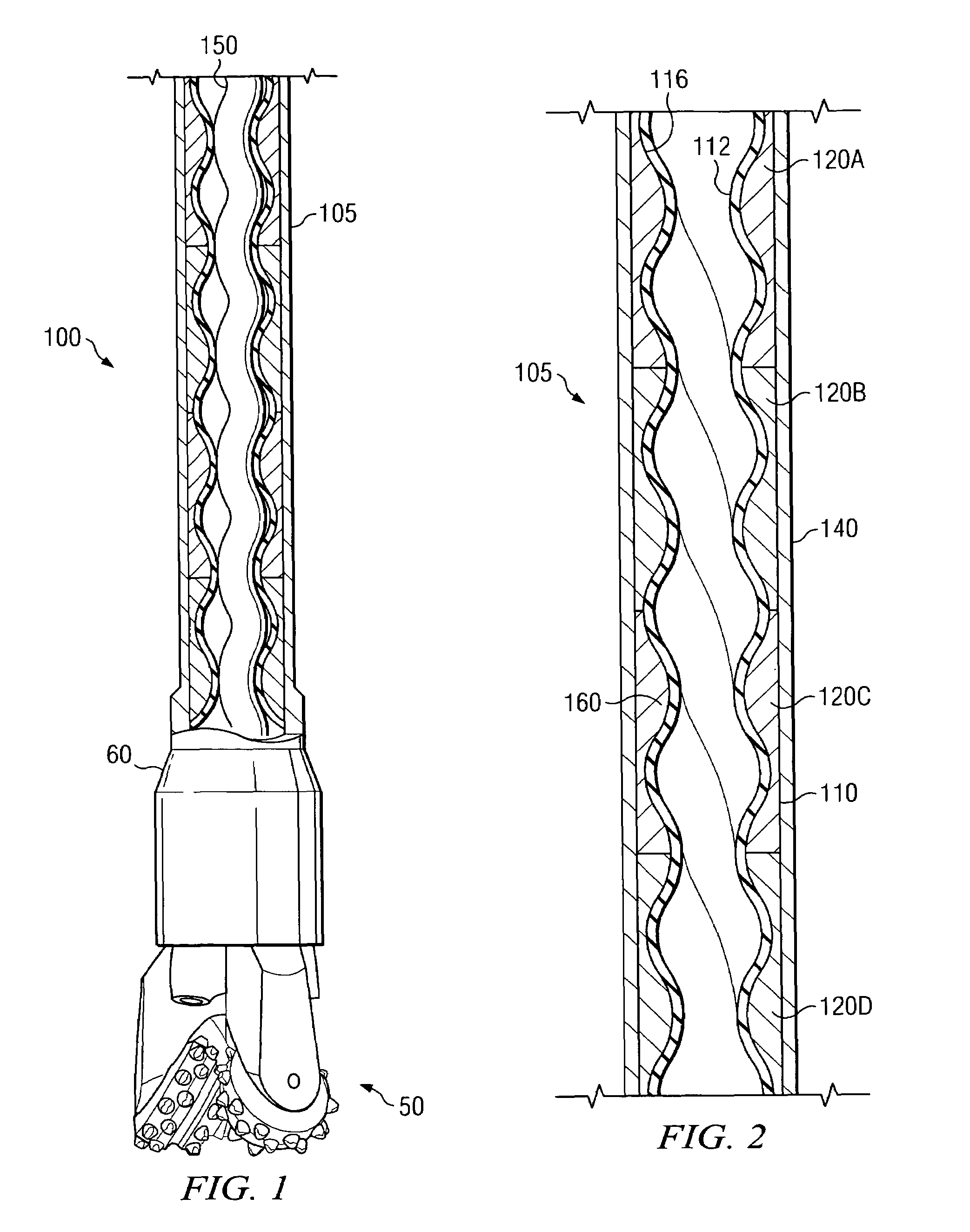
[0024]FIG. 1 illustrates one exemplary embodiment of a progressing cavity power section 100 according to this invention in use in a downhole drilling motor 60. Drilling motor 60 includes a helical rotor 150 deployed in the helical cavity of progressing cavity stator 105. In the embodiment shown on FIG. 1, drilling motor 60 is coupled to a drill bit assembly 50 in a configuration suitable, for example, for drilling a subterranean borehole, such as in an oil and / or gas bearing formation. It will be understood that the progressing cavity stator 105 of this invention, while shown coupled to a drill bit assembly in FIG. 1, is not limited to downhole applications, but rather may be utilized in substantially any application in which progressing cavity hydraulic motors and / or pumps are used.

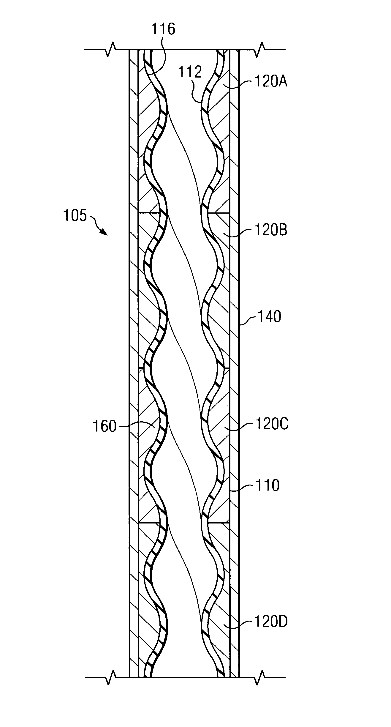
[0025]Turning now to FIG. 2, a portion of stator 105 is shown in longitudinal cross section. Progressing cavity stator 105 includes an outer stator tube 140 (e.g., a steel tube) retaining a comparatively...


PUM


Abstract

A progressing cavity stator and a method for fabricating such a stator are disclosed. Exemplary embodiments of the progressing cavity stator include a plurality of rigid longitudinal stator sections concatenated end-to-end in a stator tube. The stator sections are rotationally aligned so that each of the internal lobes extends in a substantially continuous helix from one end of the stator to the other. The stator further includes an elastomer liner deployed on an inner surface of the concatenated stator sections. Exemplary embodiments of this invention include a comparatively rigid stator having high torque output and are relatively simple and inexpensive to manufacture as compared to prior art rigid stators.

Description

RELATED APPLICATIONS[0001]This application is a continuation-in-part of co-pending, commonly-invented and commonly-assigned U.S. patent application Ser. No. 11 / 056,674 entitled PROGRESSING CAVITY STATOR HAVING A PLURALITY OF CAST LONGITUDINAL SECTIONS, filed Feb. 11, 2005.FIELD OF THE INVENTION[0002]The present invention relates generally to positive displacement progressing cavity drilling motors, typically for downhole use. This invention more specifically relates to a progressing cavity stator having a plurality of cast longitudinal sections.BACKGROUND OF THE INVENTION[0003]Progressing cavity hydraulic motors and pumps (also known in the art as Moineau style motors and pumps) are well known in subterranean drilling and artificial lift applications, such as for oil and / or gas exploration. Such progressing cavity motors make use of hydraulic power from drilling fluid to provide torque and rotary power, for example, to a drill bit assembly. The power section of a typical progressing...

Claims


Application Information

Patent Timeline
Patent Type & Authority Patents(United States)
IPC IPC(8): F01C1/10F01C5/00
CPCF04C2/1075F04C13/008F04C2240/70F04C2230/60F04C2230/00E21B4/02F03B13/02
Inventor DELPASSAND, MAJID S.NORTON, DENNIS SELL
Owner SMITH INT INC
Why Eureka
Try Eureka