Differential assembly for a machine

a technology of differential assembly and machine, applied in the direction of differential gearing, belt/chain/gearing, differential gearing, etc., can solve the problems of series of challenges, limited design in its robustness and overall structural integrity, and the components of the powertrain, in particular the differential assembly, can be subjected to extremely high loads

Active Publication Date: 2008-12-30
CATERPILLAR INC
View PDF12 Cites 16 Cited by
  • Summary
  • Abstract
  • Description
  • Claims
  • Application Information

AI Technical Summary

Problems solved by technology

While Chen may indeed achieve certain of its objectives, the design is limited in its robustness and overall structural integrity, making it suited to only certain applications.
Many larger work machines, for example certain off highway trucks, operate in environments and under conditions where components of the powertrain, and in particular the differential assembly, can be subjected to extremely high loads.
While this approach provides a relatively easy means of assembling the differential, the attempted dual purposes of the joint, i.e. joining the housing portions and constraining movement of the spider, present a series of challenges.
This invariably requires undesirable extra time and effort in the manufacturing process.
In addition, while the dual purposes of the joint would seem to provide for ease of assembly, there are often tradeoffs in terms of overall durability and wear resistance of the differential components.
This appears to be due at least in part to the fact that it is difficult to maximize the strength of the joint coupling the housing portions together without sacrificing the support function that the housing portions serve with respect to the differential spider, and vice versa.
Relatively small movements of the joint components in designs similar to the above can have the tendency to cause relatively rapid wear such as fretting in the joint faces of the bolted housing portions, the spider retention bores and surfaces of the spider itself.
This configuration can introduce wear and stress issues different from those observed with parallel axis gear interfaces for transmitting torque.
While incremental improvements have been made in some instances by increasing the bolt torque of the bolted joint between the housing portions, failure and excessive wear remains a problem.
In some cases, the wear can be severe enough to shorten the working life of the differential assembly, and prevent reuse of the differential components.
Other challenges relating to less than optimal load capacity of portions of the differential assembly can include cracking of the rotating differential housing, retention failure of thrust plates for the side gears, thread tearing on the spider when spider retention nuts are removed, and abnormal or rapid wear on the differential gears themselves.

Method used


Image

  • Differential assembly for a machine
  • Differential assembly for a machine
  • Differential assembly for a machine

Examples


Embodiment Construction

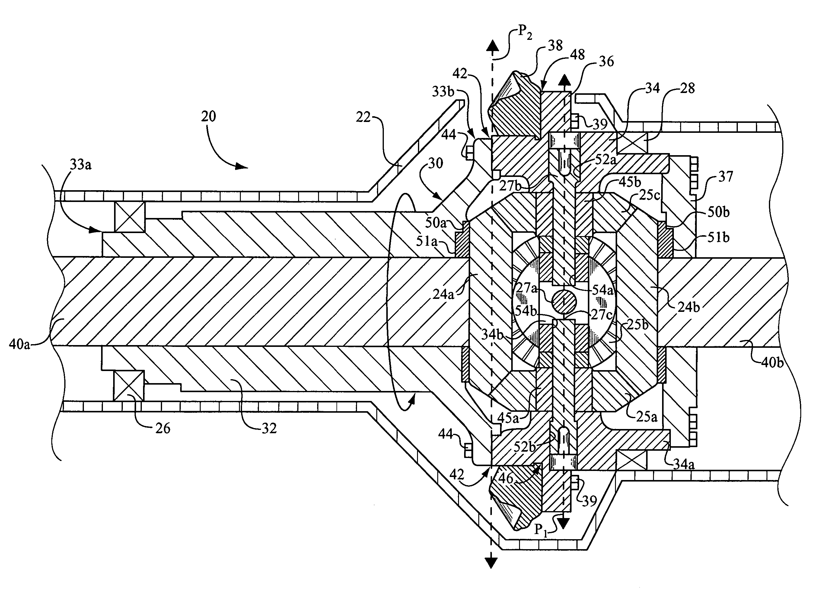
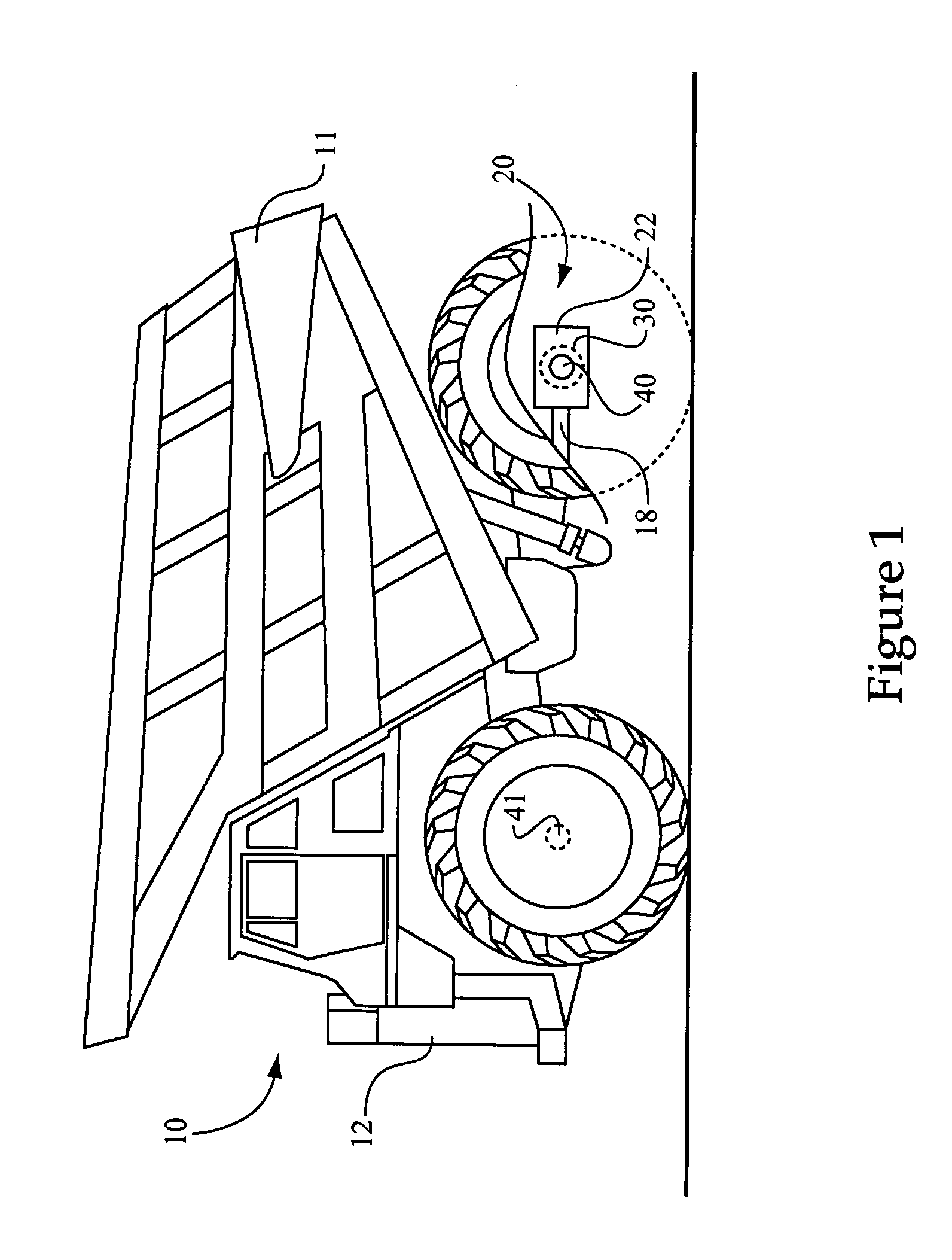
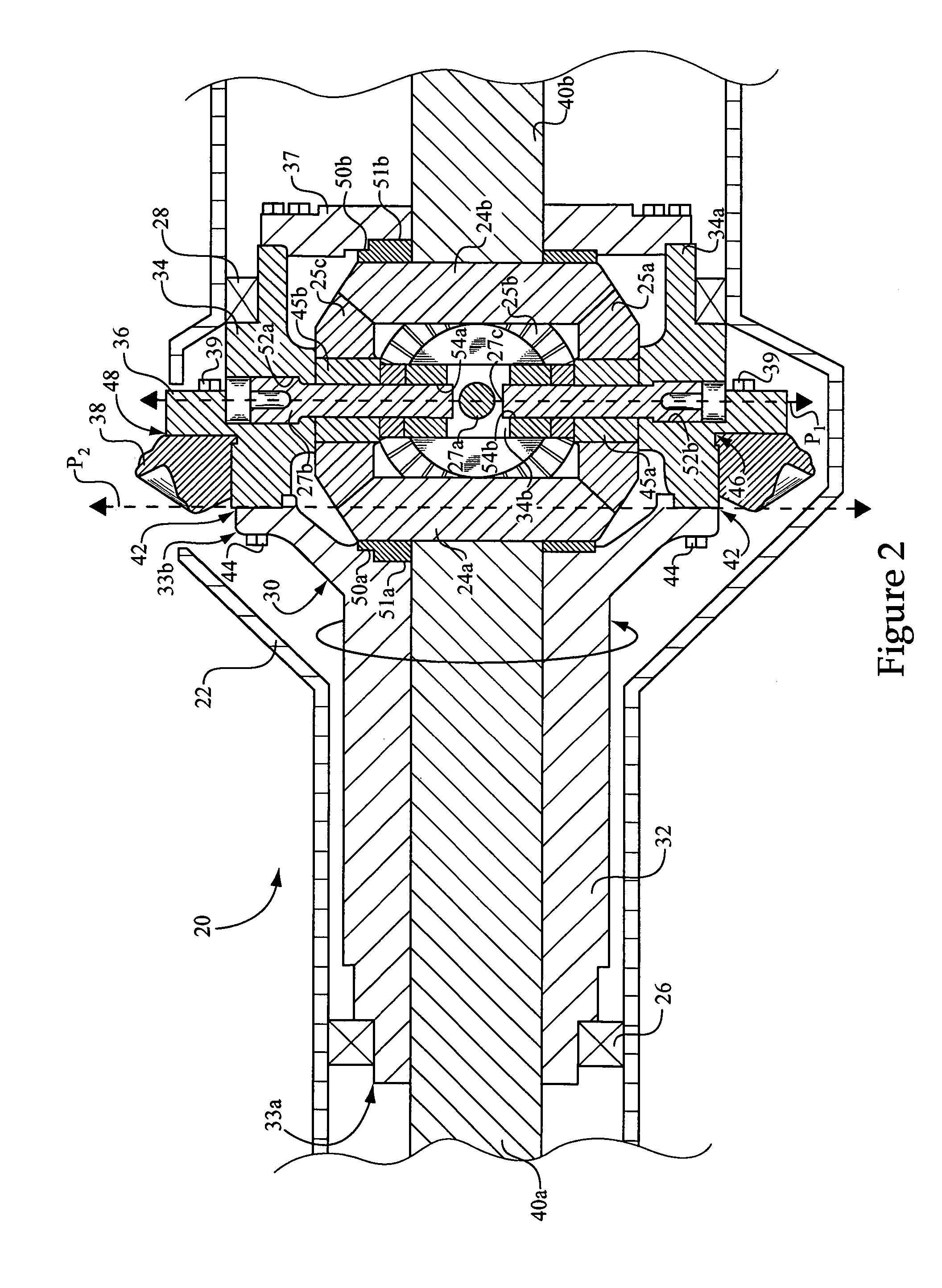
[0017]Referring to FIG. 1, there is shown a work machine 10 according to the present disclosure. Work machine 10 is shown in the context of an off-highway truck including a work machine body or frame 12 having rear and front axles 40 and 41 coupled therewith, respectively, and a payload bin 11. It should be appreciated, however, that a wide variety of both off-highway and on-highway work machines will benefit from the teachings of the present disclosure. Essentially any mobile, wheeled work machine having a differential assembly in the powertrain in accordance with the present disclosure may fall within its scope. Thus, such work machines as wheel loaders, scrapers, motor graders, on-highway trucks and even passenger vehicles are contemplated herein. Work machine 10 includes a driveshaft 18 coupled with a differential assembly, such as a rear differential assembly 20, having an outer differential housing 22 coupled to frame 12 and an inner differential housing 30 rotatably supported...


PUM


Abstract

A differential assembly for a machine includes a ring gear, first and second differential side gears and a plurality of pinions configured to mesh with the first and second side gears, and mounted on at least one pinion support pin. An inner differential housing is rotatably supported by an outer differential housing, and includes a torque transmitting hub configured to couple the ring gear with the first and second side gears via at least two pinions. The hub including a plurality of radial spokes and an outer rim portion having pinion support pin bores therein. A method of assembling a differential assembly for a machine includes coupling a spoked hub with a ring gear, and establishing a first torque transmission path between the ring gear and side gears of the differential, and establishing a second torque transmission path between a short portion of the differential housing comprising the hub and a long portion of the differential housing, the second torque transmission path including a joint coupling the short and long portions.

Description

TECHNICAL FIELD[0001]The present disclosure relates generally to differential assemblies, and relates more particularly to a differential assembly having a rotatable inner housing within an outer housing and including a spoked, torque transmitting hub.BACKGROUND[0002]Most wheeled work machines include a differential assembly in the machine's power train which allows the separate members of each set of wheels to rotate at different speeds. This capacity for rotation at different speeds, known in the art as “differentiation,” is necessary to allow smooth turning without undue stress and wear on components of the power train, as well as the work machine's tires. When a work machine navigates a turn, wheels on the outside of the turn are typically rotated more rapidly than the wheels on the inside of the turn. A typical differential will allow at least some torque to continue to be applied to each wheel, while allowing the outer wheel to rotate more rapidly than in inner wheel during tu...

Claims


Application Information

Patent Timeline
Patent Type & Authority Patents(United States)
IPC IPC(8): F16H48/06
CPCF16H48/08F16H48/40F16H2048/385
Inventor TODD, STEPHEN C.TAFT, MORRIS E.CARTER, JASON E.
Owner CATERPILLAR INC
Why Eureka
Try Eureka