Fluid flow meter with a body having upstream and downstream conical portions and an intermediate cylindrical portion

a flow meter and conical body technology, applied in the direction of measurement devices, volume/mass flow measurement, instruments, etc., can solve the problems of high manufacturing cost of coriolis measurement devices, inability to reliably measure low-density gases, and high pressure requirements of coriolis systems to operate and limit the range of operation, etc., to achieve accurate mass flow determination and inexpensive manufacturing and function.

Inactive Publication Date: 2009-02-03
NORMAN MACCRIMMON
View PDF5 Cites 6 Cited by
  • Summary
  • Abstract
  • Description
  • Claims
  • Application Information

AI Technical Summary

Benefits of technology

[0018]It is therefore an object of the present invention to provide a mass flow meter device which operates with minimal components and provides accurate and repeatable measurements.
[0032]Another object of the present invention is to provide a fluid mass flow meter device which does not require preconditioning of the inlet stream by adding lengths of conduit, providing anti-swirl mechanisms and the like.

Problems solved by technology

For example, the coriolis system requires high pressures to operate and is limited by the density of the fluids being measured.
Coriolis measurement devices are also very expensive to manufacture since they require adjunct devices and computers to determine density.
Also, coriolis flow meters do not measure low-density gases in a reliable manner and require high pressure to operate.
Non-intrusive magnetic flow meters, although not interfering with the flow being measured, require an enormous amount of electronic equipment to measure the magnetic field change of a fluid, based on magnetic flux.
Doppler sonic effect flow meters, again, are non-obtrusive, however, and associated density determining mechanisms are required to measure flow in a conduit are extremely complicated and expensive.
In addition, thermal mass meters are very expensive to manufacture and maintain.

Method used


Image

  • Fluid flow meter with a body having upstream and downstream conical portions and an intermediate cylindrical portion
  • Fluid flow meter with a body having upstream and downstream conical portions and an intermediate cylindrical portion
  • Fluid flow meter with a body having upstream and downstream conical portions and an intermediate cylindrical portion

Examples


example i

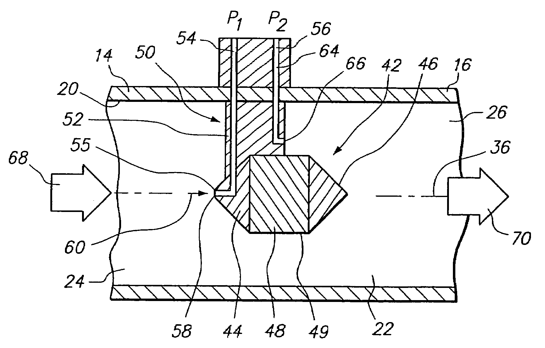
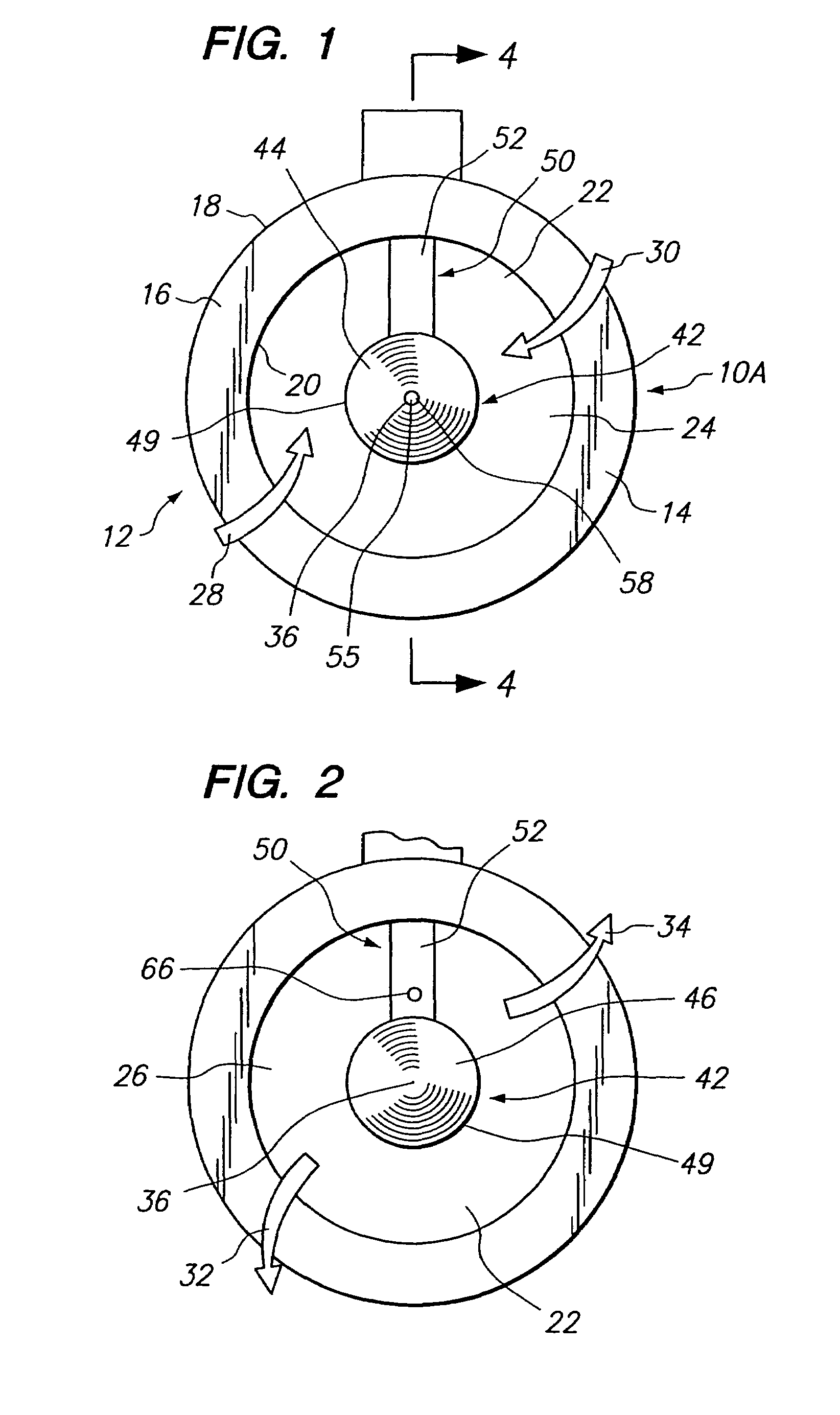
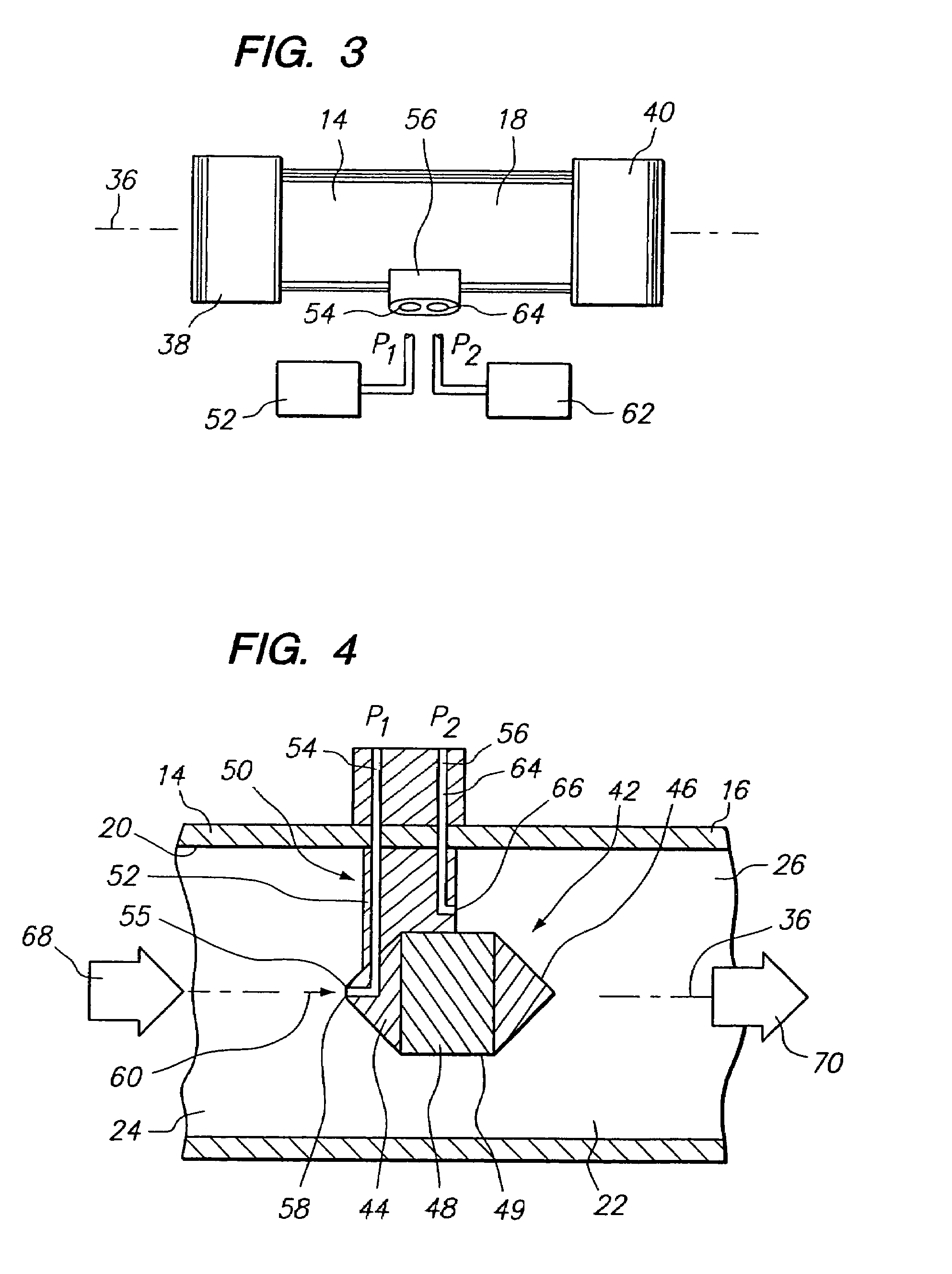
[0066]The device 10 as shown in FIGS. 1-4 was employed to determine the mass flows of the gases air and argon at room temperature and at atmosphere pressure. Argon is known to be 1.4 times as heavy as air and was employed for the sake of comparison. Device 10 was connected to a pair of pressure sensors, Model No. 860 manufactured by Autotran Incorporated of Eden Prairie, Minn. The pressure sensors were then used to determine P1 and P2 at the aperture 58 of passageway 54 and the aperture 66 of passageway 64, respectively, FIG. 4. The mass flow in pounds per second was then determined by flow rates traced through device 10 and correlated to the pressure differential, P1-P2. FIG. 6 represents the results of these tests for air and argon. Thus, for a particular sized housing, flow body 42, and chamber or annulus 22 a curve or slope was plotted for each gas. It was concluded that the curves may be extrapolated or interpolated to produce values of mass flow of either gas for a particular ...

example ii

[0067]Additional testing of the system of the present invention was accomplished using a Sensym pressure sensor employing the embodiment of the device depicted in FIG. 1. The sensor was not temperature or pressure compensated and required average readings based on an up and down pulsation at any setting. However, consistent measurements were obtained since such pulsations were stable. Such temperature and pressure variations are believed to cause errors ranging from 15 to 16 percent. In addition, the anemometer of the Sensym pressure sensor possesses an accuracy of plus or minus three percent of full scale.

[0068]Using a flow body 42, supported in a housing 12 identified as a 0.500-0.400 plastic unit, the mass flows for air were calculated in relation to various P1-P2 values, referred to as ΔP. The 0.500-0.400 plastic unit possessed an open cross-section area of about 36 percent. The pressure was measured as inches of water column. FIG. 7 represents the results obtained over various ...

example iii

[0070]The testing described in Example II was again conducted using device 10 having a flow body identified as a 0.750-0.375 plastic unit. The cross-sectional area of the flow body of 0.750-0.375 unit relative to the cross-sectional area of the chamber 22 of housing 12 produces an open area of greater than 70 percent. Air was passed through device 10 with the 0.750-0.375 flow body and the results were calculated in FIGS. 12 and 13 as a comparison between mass flow and P1-P2. In this “standard direction” the curved graph result of FIG. 12 was transformed into a straight line, again, by taking the square root of the P1-P2 values. This result is shown in FIG. 13.

[0071]Referring now to FIG. 11, the flow body 42 was reversed such that opening 55 faced exit 26 of chamber 22 and opening 66 faced entrance 24 to chamber 22. This “reverse direction” orientation was then employed in the same manner as described hereinabove in the present Example. FIGS. 14 and 15 represent the mass flow determi...


PUM


Abstract

A mass flow meter device utilizing a housing having a wall portion forming a chamber with an entrance and exit for passing fluid through the same. A body is located within the chamber and is composed of a first conical portion, a second conical portion, and a cylindrical portion positioned intermediate the first and second conical portions. The body is held within the chamber in a standard or reverse direction. A first pressure probe or sensor measures the fluid pressure at the apex of the first conical portion while a second pressure probe or sensor obtains a second pressure measurement at the cylindrical portion of the body. The comparison of the first and second pressure measurements serves as an indication for the mass flow of fluid through the housing.

Description

CROSS-REFERENCES TO RELATED APPLICATIONS[0001]The present application is related to provisional application Ser. No. 60 / 373,549, filed 17 Apr. 2002.BACKGROUND OF THE INVENTION[0002]The present invention relates to a novel and useful fluid mass flow metering device.[0003]Mass flow meters are often used in conjunction with other mechanical entities such as micro-atomizers, oxygen delivery systems, valve controlled devices, pressure regulators, compressors, and pumps.[0004]In the past, mass flow meters have taken various forms. For example, the coriolis system requires high pressures to operate and is limited by the density of the fluids being measured. Coriolis measurement devices are also very expensive to manufacture since they require adjunct devices and computers to determine density. Also, coriolis flow meters do not measure low-density gases in a reliable manner and require high pressure to operate.[0005]Non-intrusive magnetic flow meters, although not interfering with the flow ...

Claims


Application Information

Patent Timeline
Patent Type & Authority Patents(United States)
IPC IPC(8): G01F1/37
CPCG01F1/363G01F1/40
Inventor HUGHES, NATHANIELSHAW, LEON
Owner NORMAN MACCRIMMON
Why Eureka
Try Eureka