Method for strength testing of drawers in computer rack systems

Inactive Publication Date: 2009-04-28
IBM CORP
View PDF7 Cites 1 Cited by
  • Summary
  • Abstract
  • Description
  • Claims
  • Application Information

AI Technical Summary

Benefits of technology

[0009]As a result of the summarized invention, technically we have achieved a testing apparatus and method which is capabl

Problems solved by technology

Failure of the slide rail, the cabinet, or the drawer under load could lead to damage of the electronic components, and / or injury to a technician working at the cabinet.

Method used


Image

  • Method for strength testing of drawers in computer rack systems
  • Method for strength testing of drawers in computer rack systems
  • Method for strength testing of drawers in computer rack systems

Examples


Embodiment Construction

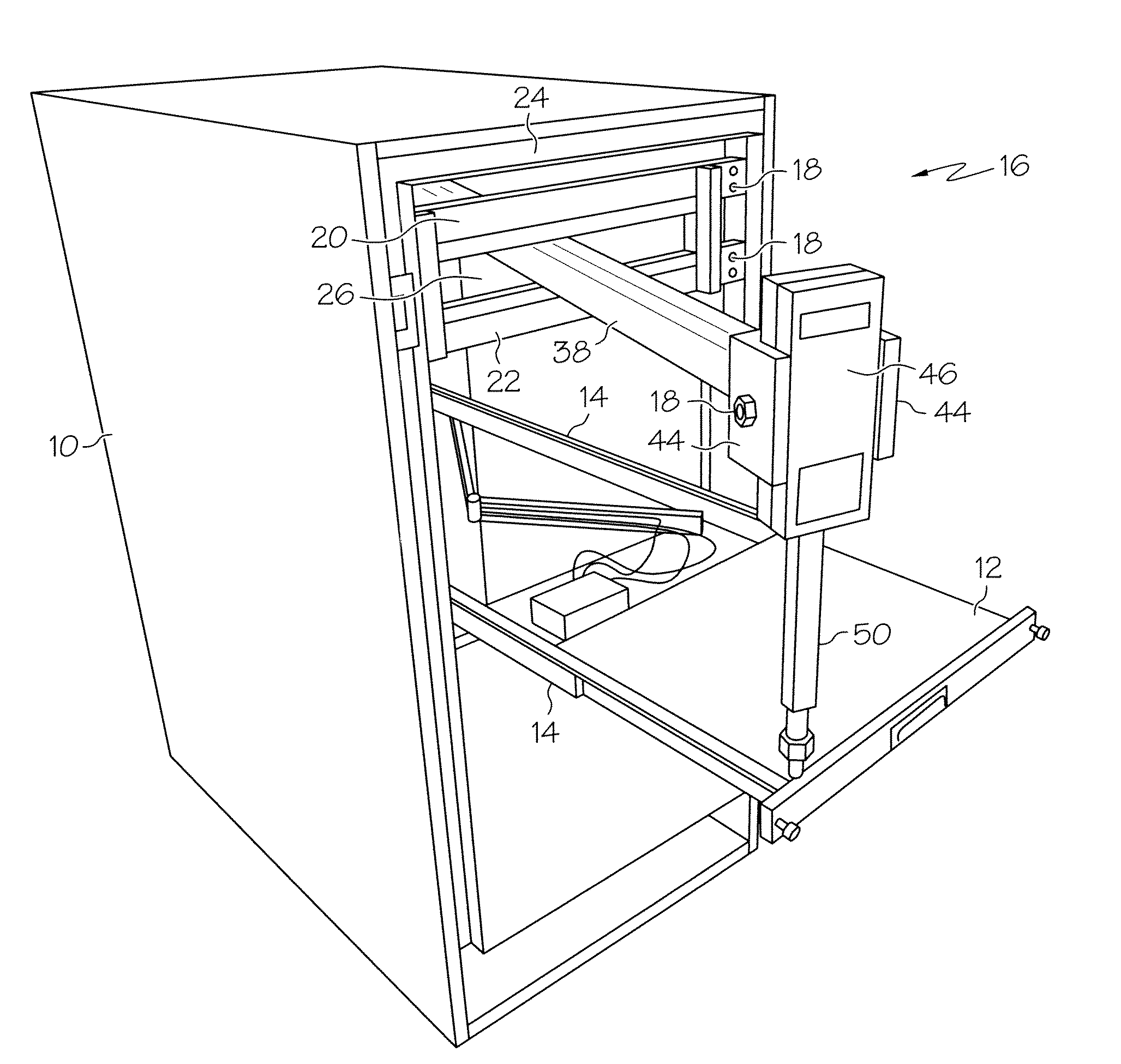
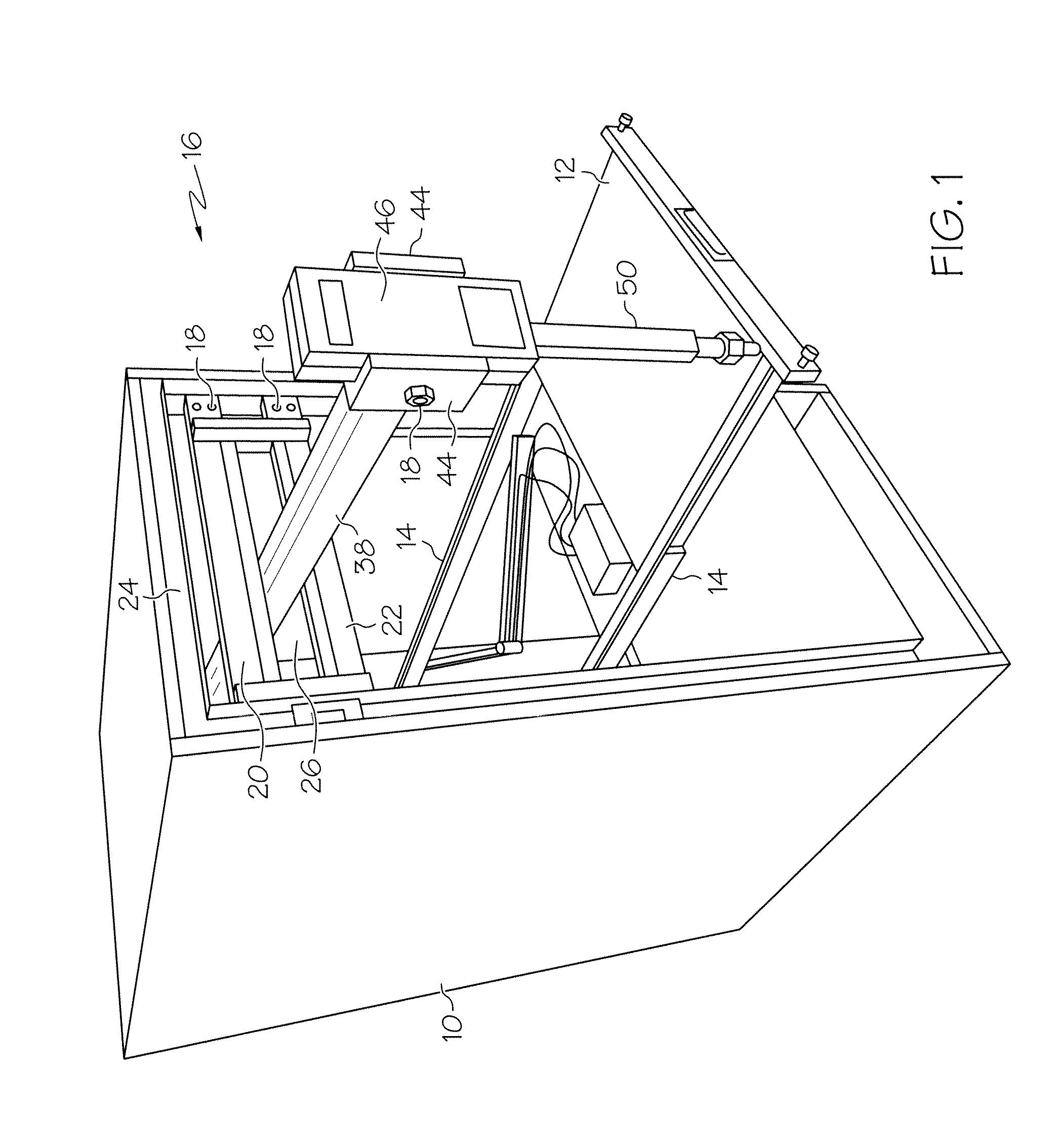
[0014]Turning now to the drawings in greater detail, it will be seen that in FIG. 1 there is an enclosure 10 which has at least one drawer 12 disposed and configured to accommodate one or more electronic components (not shown) in the enclosure 10. The drawer 12 is attached to the enclosure 10 via two slide rail mechanisms 14 which allow the drawer 12 to be moved in and out of the enclosure 10.

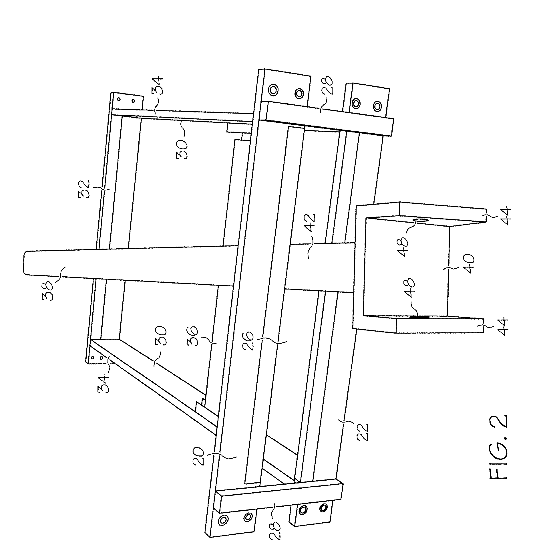
[0015]A test apparatus 16 is located in the enclosure 10, and is fixed to a front face 18 of the enclosure 10 by one or more threaded fasteners 18 or other means. The test apparatus 16 includes an upper front plate 20 and a lower front plate 22 which extend across a front opening 24 of the enclosure 10 and are configured such that a front slot 26 remains between the upper front plate 20 and lower front plate 22. As best shown in FIG. 2, the upper front plate 20 is connected to the lower front plate 22 via two or more end plates 28 which may be attached to the upper front plate 20 and lower fron...


PUM


Abstract

Disclosed is a method of strength testing of a drawer of a computer rack system. The method utilizes a test apparatus including a first apparatus plate and a second apparatus plate positioned to define an apparatus slot between the first apparatus plate and the second apparatus plate. The apparatus includes a moveable positioning arm disposed in the apparatus slot, the moveable positioning arm including a holder portion, a force gauge secured to the holder portion; and a force applicator operably connected to the force gauge. The test apparatus is secured to an enclosure of the computer rack system and the drawer is located in a desired position in the enclosure. The force applicator is positioned such that the force applicator contacts the drawer at a testing location, and a force is applied to the testing location via the force applicator.

Description

TRADEMARKS[0001]IBM® is a registered trademark of International Business Machines Corporation, Armonk, N.Y., U.S.A. Other names used herein may be registered trademarks, trademarks or product names of International Business Machines Corporation or other companies.BACKGROUND OF THE INVENTION[0002]1. Field of the Invention[0003]This invention relates to computer rack systems, and particularly to force testing of drawers of computer rack systems.[0004]2. Description of Background[0005]Rack systems for, for example, computer servers typically include a cabinet or other enclosure having one or more drawers which hold electronic components. The drawers often include a slide mechanism in which the drawer is connected to the cabinet via slide rails. This allows the electronic components located on the drawer to be accessed for maintenance and / or replacement by sliding the drawer partially out of the cabinet.[0006]Cabinets and slide rail drawers are designed and manufactured to meet load req...

Claims


Application Information

Patent Timeline
IPC IPC(8): G01B5/30
CPCG01M99/007
Inventor BAILEY, DAVID J.HYLAND, ROBERT F.MISGEN, MARVIN M.PRISCO, JOSEPH F.
Owner IBM CORP
Why Eureka
Try Eureka