Display unit and backlight unit

a backlight unit and display technology, applied in the field of display units and backlight units, can solve the problem of not being practicable to individually drive leds that make up the backlight units, and achieve the effect of eliminating the variation of display brightness

Inactive Publication Date: 2009-03-31
SATURN LICENSING LLC
View PDF16 Cites 97 Cited by
  • Summary
  • Abstract
  • Description
  • Claims
  • Application Information

AI Technical Summary

Benefits of technology

[0012]Also, the sorrounding air in the display unit is warmed up by the heat generated by LEDs and the relative density of the air decreases. As a result, the air in the display unit rises upwards.
[0015]One way to tackle this problem is to eliminate the variation of display brightness due to temperature distribution.
[0016]The gist of the present invention resides in a backlight unit installed in the back of a display unit, which includes a lighting unit composed of a plurality of LEDs connected in series, a drive unit to drive LEDs in the lighting unit, each drive unit corresponding to each lighting unit, and a temperature detecting unit to detect the temperature of each lighting unit, the lighting units being arranged in various positions at which the LEDs keep a prescribed temperature, and the drive units controlling current to be supplied to the LEDs in each lighting unit according to the temperature of each lighting unit, which is detected by the temperature detecting unit, so that each lighting unit keeps brightness uniform even though each lighting unit changes in temperature.
[0017]According to one embodiment of the present invention, the LEDs in each lighting unit are arranged in series horizontally and the lighting units are arranged at positions where the temperature is approximately the same because of the temperature distribution resulting from the heat generation of the lighting unit per se. Therefore, the drive unit controls current to be supplied to LEDs in each lighting unit according to the temperature, which is detected by the temperature detecting unit, thereby keeping the backlight unit uniform in brightness even though the lighting unit changes in temperature.

Problems solved by technology

The disadvantage of using LEDs as the light source is the necessity of supplying red LEDs, green LEDs, and blue LEDs with current independently because they differ in luminous efficiency.
However, it is not practical to individually drive LEDs constituting the backlight unit.

Method used


Image

  • Display unit and backlight unit
  • Display unit and backlight unit
  • Display unit and backlight unit

Examples


Embodiment Construction

[0036]The embodiments of the present invention will be described in more detail with reference to the accompanying drawings.

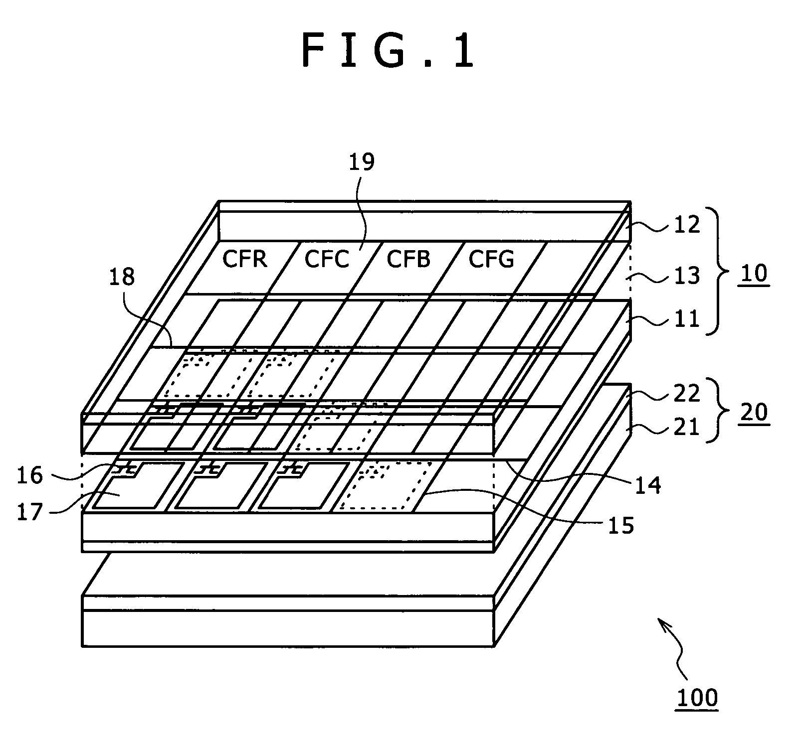
[0037]The present invention is applicable to the color liquid crystal unit 100 of backlight type constructed as shown in FIG. 1.

[0038]The color liquid crystal display unit 100 consists of a color display panel 10 of transmissive type and a backlight unit 20 placed behind the color display panel 10.

[0039]The color liquid crystal display panel 10 of transmissive type has the TFT substrate 11 and the opposed electrode substrate 12, which face each other with the liquid crystal layer 13 (of twisted nematic TN liquid crystal) interposed between them. The TFT substrate 11 has signal lines 14 and scanning lines 15 formed thereon in a matrix pattern. At their intersections are formed thin-film transistors 16 (as switching elements) and pixel electrodes 17. The thin film transistors 16 are sequentially selected by the scanning lines 15; they also write the image signals...


PUM


Abstract

The screen is exempt from variation in brightness due to uneven temperature distribution.The color liquid crystal display unit has a color display panel of transmissive type and a backlight unit placed behind the color display panel. The backlight unit has a plurality of LEDs connected in series, the drive unit to drive the LEDs in correspondence with the LEDs, and the temperature sensor to detect the temperature of LEDs. The groups of LEDs are arranged in regions where the display unit has the same temperature. The drive unit controls current to be supplied to LEDs in response to temperature detected by the temperature sensor so that the LEDs retain the constant brightness even when the LEDs fluctuate in temperature.

Description

BACKGROUND OF THE INVENTION[0001]The present invention relates to a display unit with a non-luminous screen of transmissive-type and also to a backlight unit placed behind the screen.[0002]Liquid crystal panels are usually provided with a backlight unit composed of cold cathode fluorescent lamps (CCFL). However, there is a demand for a mercury-free backlight unit from the standpoint of environmental protection. Light emitting diodes (LEDs) are regarded as promising in this respect as a substitute for CCFLs. Application of LEDs to televisions is under meticulous research because of their ability to produce a well-balanced white color by optical color mixing from LEDs emitting red, green, and blue elementary colors.[0003]The disadvantage of using LEDs as the light source is the necessity of supplying red LEDs, green LEDs, and blue LEDs with current independently because they differ in luminous efficiency. Moreover, LEDs vary in their semiconductor compositions depending on their emitt...

Claims


Application Information

Patent Timeline
Patent Type & Authority Patents(United States)
IPC IPC(8): G09G3/36
CPCG02F1/133603G09G3/3413G09G3/342G09G2320/0233G09G2320/041G09G2320/0633G09G2320/064G09G2360/145G02F1/133
Inventor FURUKAWA, NORIMASAKIKUCHI, KENICHIICHIKAWA, HIROAKI
Owner SATURN LICENSING LLC
Why Eureka
Try Eureka