Unlock instant, AI-driven research and patent intelligence for your innovation.

Image forming apparatus and method that identify halftone process parameter

a technology of image forming and process parameters, applied in electrographic process apparatus, instruments, optics, etc., can solve problems such as difficulty in controlling the development conditions, and unstable image forming density

Active Publication Date: 2009-03-31
CANON KK
View PDF6 Cites 4 Cited by
  • Summary
  • Abstract
  • Description
  • Claims
  • Application Information

AI Technical Summary

Benefits of technology

The present invention is an image forming apparatus that can identify a process parameter of a halftone process and create a patch image based on that parameter. The density of the patch image is then detected, and the image forming conditions are adjusted accordingly. This allows for appropriate adjustment of the image forming conditions even if the halftone-processed image data is inputted. The technical effect of this invention is to provide a more efficient and effective method for adjusting image forming conditions.

Problems solved by technology

Generally, in electrophotographic image forming apparatus, image forming density (e.g., the amount of color material) becomes unstable due to variations in each part (e.g., amount of electric charge retained in color material) and variations in installation environment (e.g., temperature and humidity).
The image forming density also becomes unstable by variations in sensitivity of photosensitive material and environmental variations in transfer member.
However, the method of controlling developing conditions has a difficulty, since control response is typically low when developing conditions is changed.
That is, there is a drawback in that it takes relatively longer time to settle the variation.
As a result, when halftone-processed image is inputted, the method of modifying the γLUT using the patch image no longer makes sense.

Method used


Image

  • Image forming apparatus and method that identify halftone process parameter
  • Image forming apparatus and method that identify halftone process parameter
  • Image forming apparatus and method that identify halftone process parameter

Examples


first embodiment

[0033]FIG. 1 is an exemplary configuration of an image forming apparatus according to an embodiment. Here, as an example of the image forming apparatus, an electrophotographic color laser beam printer 100 is used.

[0034]The printer 100 employs a so-called rotary-type image forming station. Of course, the present invention can also be applied to a tandem-type image forming station. The tandem-type image forming station is typically made of a plurality of image forming units arranged in parallel and an intermediate transfer belt. The configuration of the tandem-type image forming station is well-known to those skilled in the art, and therefore not described in detail.

[0035]A light emitting part (scanner part) 101 is made of an optical source, a polygon mirror, etc. Output light 102 from the optical source (e.g., laser diode or LED) is modulated by an image data for each color component obtained from a print data. An electrostatic latent image is formed by scanning a photosensitive drum...

second embodiment

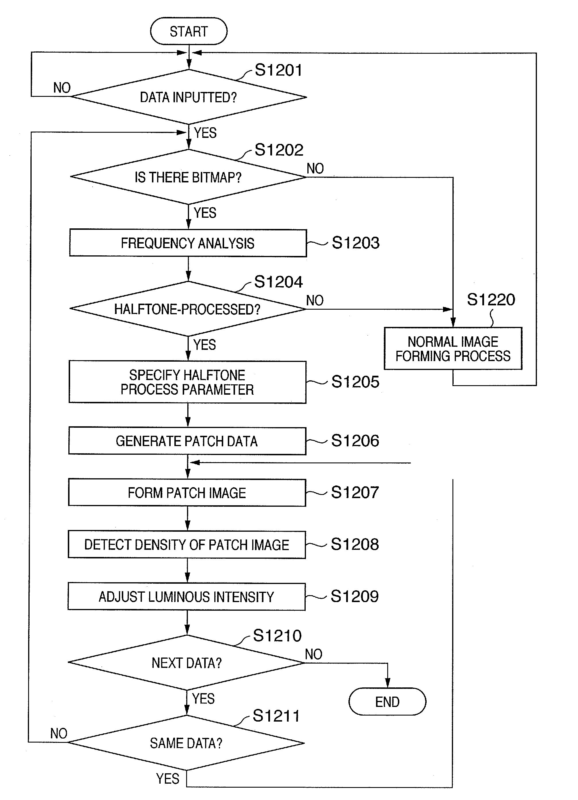
[0087]FIG. 12 is a detailed and exemplary flow chart for stability control according to a second embodiment. In the present embodiment, a more detailed example for stability control is described.

[0088]In step S1201, The CPU 201 in the controller part 200 determines whether or not the data for printing generated at a PC or another server is inputted through the interface part 205. If the data for printing is inputted, the process proceeds to step S1202.

[0089]In step S1202, the CPU 201 determines whether there is a bitmap image in the inputted data using the halftone identifying part 206. If there is not a bitmap image in the data for printing, for example it is a normal text data, the process proceeds to step S1220, where the CPU 201 performs a normal image forming process. The normal image forming process refers to an image forming process in which stability control (adjustment of image forming conditions) according to the present embodiment is skipped. When the normal image forming...

third embodiment

[0101]In the second embodiment, the example of primarily adjusting the luminous intensity of laser (LPW) depending on the density of the patch image has been described. Typically, in order to change LPW, it is required to change bias. Therefore, when bias is switched for each color with respect to light emission of laser, response time for switching may decrease processing speed. Cost may also be increased.

[0102]In a third embodiment, an example of adjusting light emission duration of laser by controlling the pulse width of an image signal inputted to the laser will be described. In general, PWM (pulse width modulation) scheme is applied to the light emitting part 101. Therefore, adjusting light emission duration of laser has an advantage over adjusting luminous intensity of laser in that it is relatively easy to provide it.

[0103]In PWM scheme, since light emission duration at a place where there is a dot can be changed even in a binary image, similar effect as controlling luminous ...


PUM


Abstract

An image forming apparatus appropriately adjusts an image forming conditions even if a halftone-processed image data is inputted. The image forming apparatus forms a patch image by applying a halftone process which is substantially equivalent to the halftone process which has been previously performed for the inputted image data. The image forming apparatus detects the density of the formed patch image and adjusts the image forming conditions according to the detected density.

Description

BACKGROUND OF THE INVENTION[0001]1. Field of the Invention[0002]The present invention relates to an image forming technology.[0003]2. Description of the Related Art[0004]It is important to stabilize the quality of an image formed in image forming devices. Generally, in electrophotographic image forming apparatus, image forming density (e.g., the amount of color material) becomes unstable due to variations in each part (e.g., amount of electric charge retained in color material) and variations in installation environment (e.g., temperature and humidity). The image forming density also becomes unstable by variations in sensitivity of photosensitive material and environmental variations in transfer member.[0005]As an approach for stabilizing formed images, a method of controlling developing conditions (Japanese Patent Application Laid-Open No. 09-319270) or a method of modifying image data (Japanese Patent Application Laid-Open No. 2003-228201) are generally used.[0006]In the method of...

Claims


Application Information

Patent Timeline
Patent Type & Authority Patents(United States)
IPC IPC(8): G03G15/00G03G15/10
CPCG03G15/0131G03G15/5058G03G15/0121G03G15/0173G03G2215/00059G03G2215/00063G03G2215/0106
Inventor ITAGAKI, TOMOHISA
Owner CANON KK