
Negative coefficient of thermal expansion particles and method of forming the same
a technology of thermal expansion particle and negative coefficient, which is applied in the direction of coupling device connection, synthetic resin layered product, non-conductive material with dispersed conductive material, etc., can solve the problem of limited extent to which the cte of a material can be thus reduced, and the improvement over siosub>2 is only moderate, so as to eliminate or reduce the problem of association
- Summary
- Abstract
- Description
- Claims
- Application Information
AI Technical Summary
Benefits of technology
Problems solved by technology
Method used
Image

Examples
Embodiment Construction
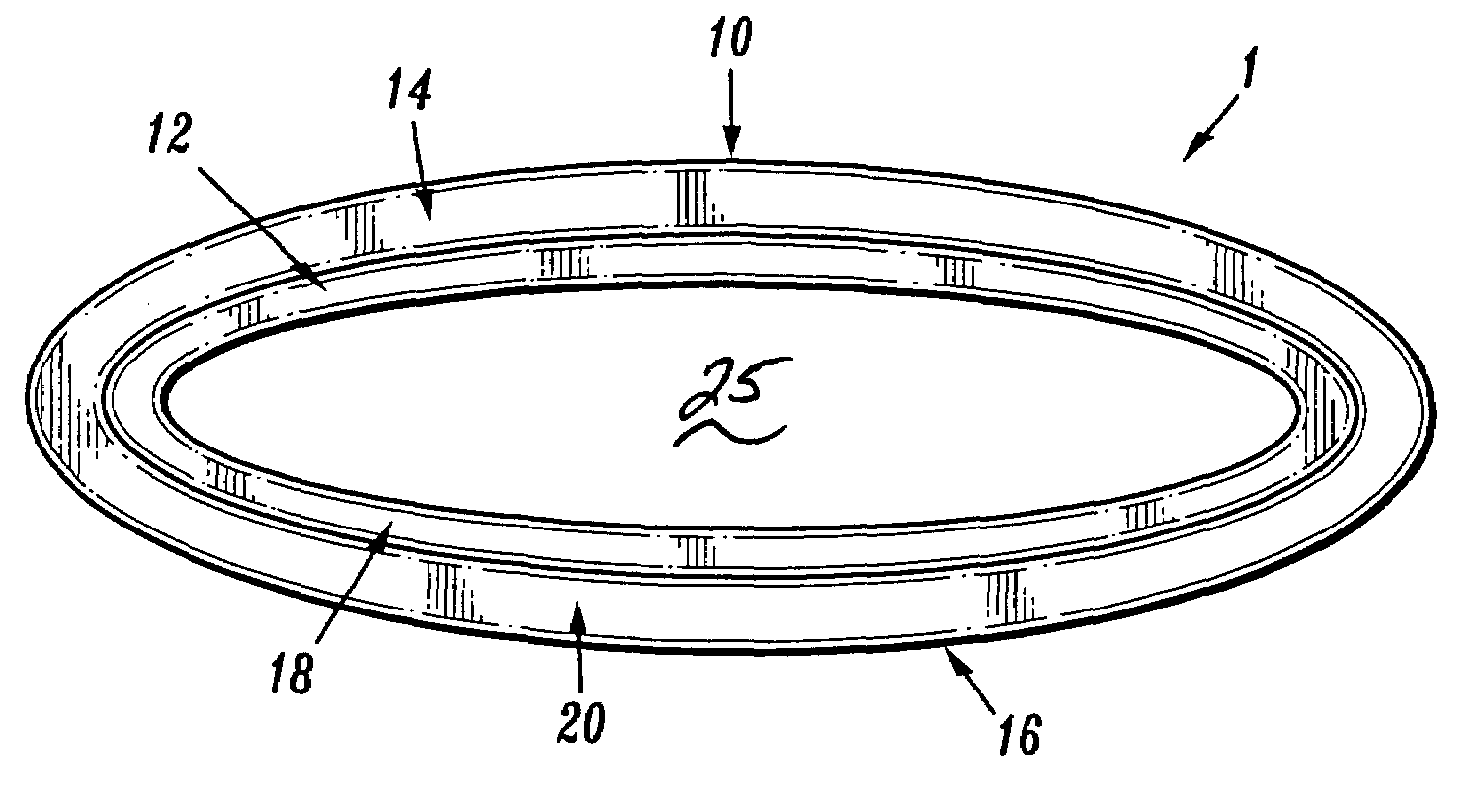
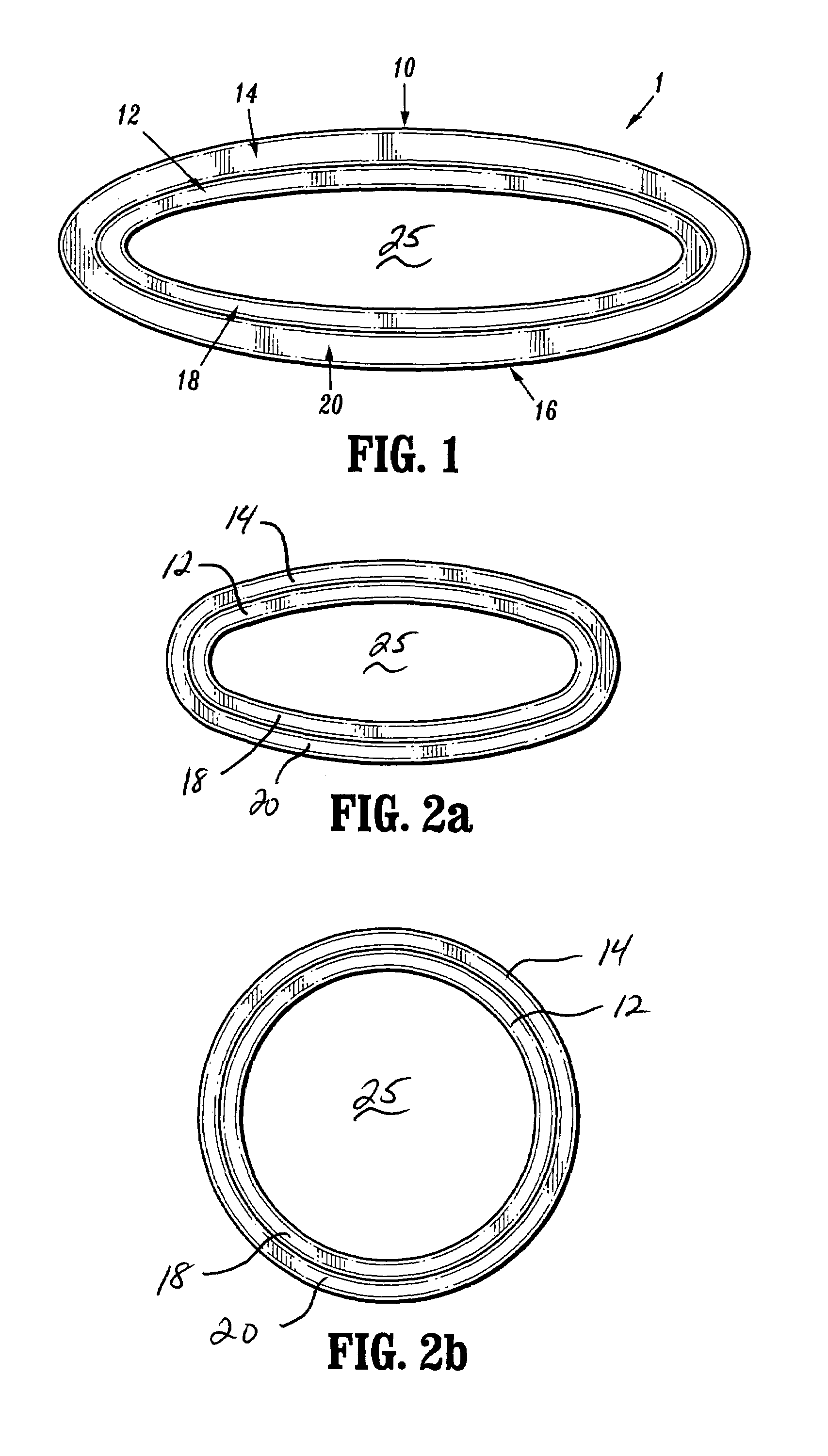
[0026]FIG. 1 is a cross sectional view of a negative CTE particle 1 according to an exemplary embodiment of the invention. The negative CTE particle 1 includes a first bilayer 10 having an inner layer 12 and an outer layer 14, and a second bilayer 16 having an inner layer 18 and an outer layer 20. The inner layer 12 of the first bilayer 10 faces the inner layer 18 of the second bilayer 16. The inner layers 12 and 18 are joined together along a perimeter of the inner layers 12 and 18, and the outer layers 14 and 20 are joined together along a perimeter of the outer layers 14 and 20. The inner layers 12 and 18 have a higher CTE than that of the outer layers 14 and 20. The bilayers 10 and 16 have adequate strength and flexibility such that they will bend elastically in response to temperature induced stress. The bilayers 10 and 16 can be formed of any suitable materials, such as, for example, metals, glass, polymers, metal oxides, carbides, nitrides, and alloys.
[0027]FIGS. 2a-2b show c...
PUM
| Property | Measurement | Unit |
|---|---|---|
| temperatures | aaaaa | aaaaa |
| CTE | aaaaa | aaaaa |
| coefficient of thermal expansion | aaaaa | aaaaa |
Abstract
Description
Claims
Application Information