Maintaining photoresist planarity at hole edges

Inactive Publication Date: 2006-02-28
TAIWAN SEMICON MFG CO LTD
View PDF11 Cites 3 Cited by
  • Summary
  • Abstract
  • Description
  • Claims
  • Application Information

AI Technical Summary

Benefits of technology

[0016]These objects have been achieved by laying down the photoresist as two separate layers. The first layer is used to eliminate or reduce problems associated with coating a surface that includes cavities. The second layer is processed in the normal way and does not introduce distortions close to a cavity's edge. A first embodiment introduces some liquid into the cavity before laying down the first layer while the second embodiment etches away part of the first layer before applying the second one. Application of the process to the formation of a cantilever that overhangs a cavity is also described.

Problems solved by technology

Maintaining photoresist thickness and uniformity under these conditions often presents a major challenge.
1. Because of its viscosity, the photoresist is unable to completely fill deep holes.
2. Bubbles may get trapped within the photoresist used to fill the holes subsequently leading to cracks generated during routine baking of the resist.
3. Photoresist uniformity is poor close to a high topography border, in particular a cavity in the form of a trench or a via hole or a channel (e.g. for conveying fluid),
The upward movement of resist 16 to a new peak height 43 becomes permanent because of the resist hardening so, even after cooling, openings 31 have become distorted and uneven so that subsequent attempts to etch through them, or to use them as molds, produce poor results.

Method used


Image

  • Maintaining photoresist planarity at hole edges
  • Maintaining photoresist planarity at hole edges
  • Maintaining photoresist planarity at hole edges

Examples


Embodiment Construction

[0029]We will describe the invention in terms of photoresist but it should be understood that the invention is more general than this and is applicable to any material that is radiation-sensitive and patternable.

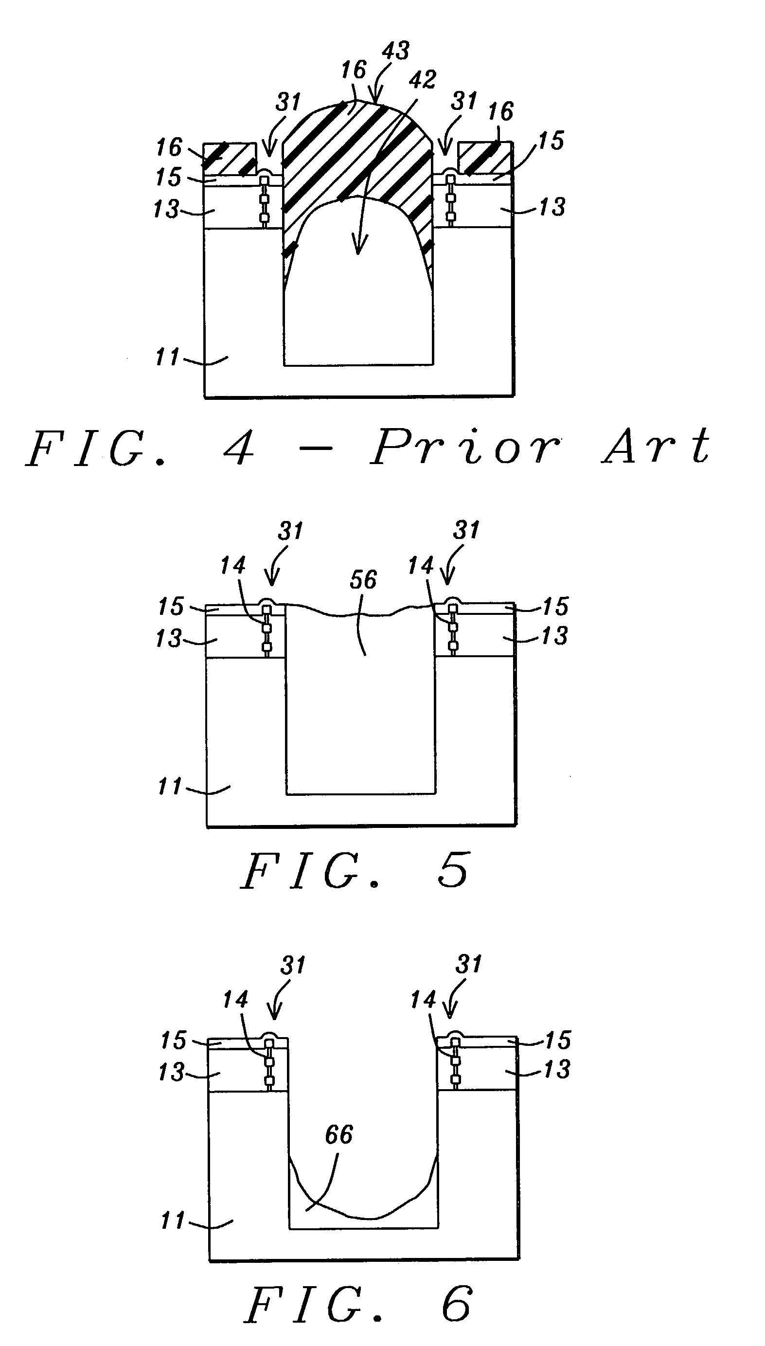
[0030]Referring now to FIG. 5, a first embodiment of the process of the present invention begins with the provision a substrate (base 11 together with layers 13 and 15 in this example) in whose upper surface there is a cavity in the form of a trench, a via hole, or liquid channel. The cavity has a depth between about 15 and 25 microns and a width between about 13 and 18 microns. In a departure from prior art practice, the next step is to fill this cavity with liquid 56 that dissolves photoresist and wets the cavity's floor and sidewalls. Typical examples of such a liquid include (but are not limited to) OK73 Thinner, propylene glycol monomethyl ether 7%, and propylene glycol monomethyl ether acetete.

[0031]Next, most of liquid 56 is removed from within the cavity (preferably ...


PUM

PropertyMeasurementUnit
Temperatureaaaaaaaaaa

Abstract

Maintaining photoresist thickness and uniformity over a substrate that includes various cavities presents problems, such as preventing distortion of features in the resist image close to cavity edges. These problems have been overcome by laying down the photoresist as two separate layers. The first layer is used to eliminate or reduce problems associated with the presence of the cavities. The second layer is processed in the normal way and does not introduce distortions close to a cavity's edge. A first embodiment introduces some liquid into the cavity before laying down the first layer while the second embodiment etches away part of the first layer before applying the second one. Application of the process to the formation of a cantilever that overhangs a cavity is also described.

Description

FIELD OF THE INVENTION[0001]The invention relates to the general field of integrated circuits with particular reference to application of photoresist to surfaces in which there are cavities.BACKGROUND OF THE INVENTION[0002]During the manufacture of custom integrated circuits, it may be required that deep holes be fully filled with photoresist. Maintaining photoresist thickness and uniformity under these conditions often presents a major challenge. In particular, if it is necessary to include, as part of the photoresist image, a feature (such as a hole or an island) that is located within about 25 microns from the edge of a cavity, conventional methods for photoresist coating suffer from three serious problems:[0003]1. Because of its viscosity, the photoresist is unable to completely fill deep holes.[0004]2. Bubbles may get trapped within the photoresist used to fill the holes subsequently leading to cracks generated during routine baking of the resist.[0005]3. Photoresist uniformity...

Claims


Application Information

Patent Timeline
IPC IPC(8): G03F7/00G03F7/16G03F7/26H01L21/312
CPCH01L21/312G03F7/0035H01L21/022H01L21/02282
Inventor CHENG, SU-JENJANG, BOR-PINGWANG, CHUN-CHIEHGAU, JY-JIE
Owner TAIWAN SEMICON MFG CO LTD
Why Eureka
Try Eureka