Pickup device driving apparatus, photographing device using the same, and monitoring camera apparatus

a technology of driving apparatus and photographing device, which is applied in the field of photographing apparatus, can solve the problems of reducing driving precision and achieve the effect of high driving precision and high driving precision

Active Publication Date: 2009-10-27
PANASONIC I PRO SENSING SOLUTIONS CO LTD
View PDF11 Cites 3 Cited by
  • Summary
  • Abstract
  • Description
  • Claims
  • Application Information

AI Technical Summary

Benefits of technology

[0009]An object of the present invention is to provide a pickup device having high driving precision even upon the slight movement, a photographing apparatus using the same, and a monitoring camera apparatus.

Problems solved by technology

In particular, even when the pickup device is slightly moved, linearity of the movement distance of the pickup device due to rotation of the lead screw deteriorates and thus driving precision is reduced.

Method used


Image

  • Pickup device driving apparatus, photographing device using the same, and monitoring camera apparatus
  • Pickup device driving apparatus, photographing device using the same, and monitoring camera apparatus
  • Pickup device driving apparatus, photographing device using the same, and monitoring camera apparatus

Examples


embodiment

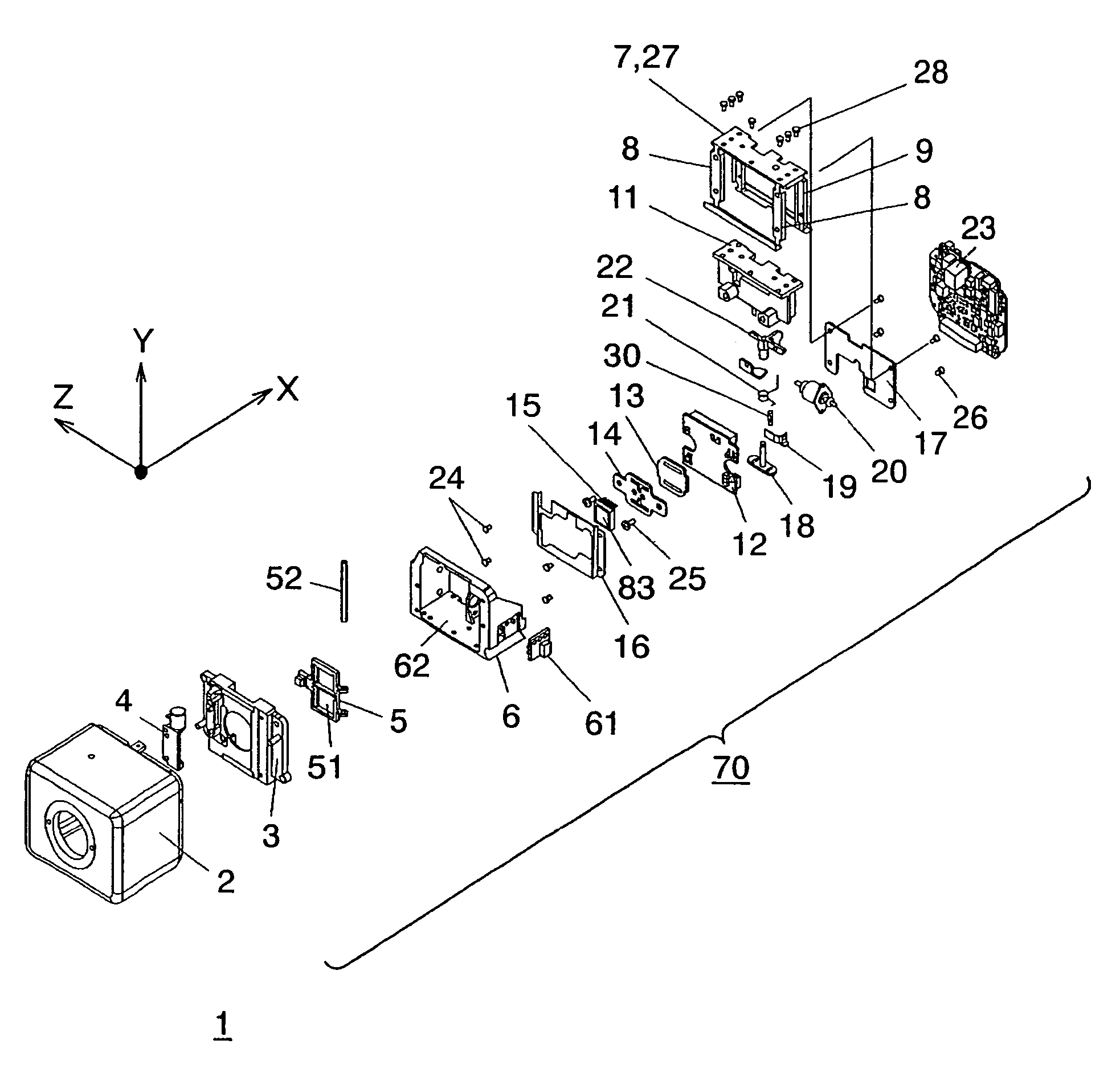
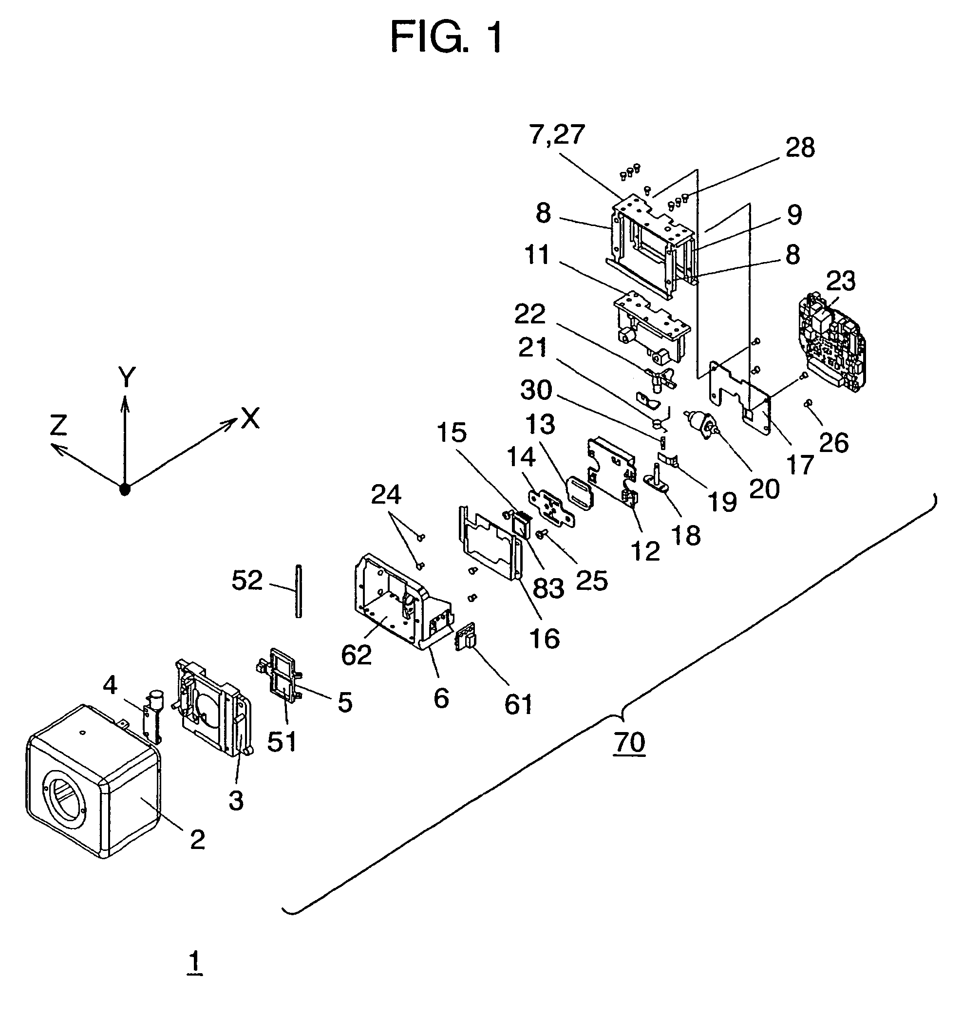
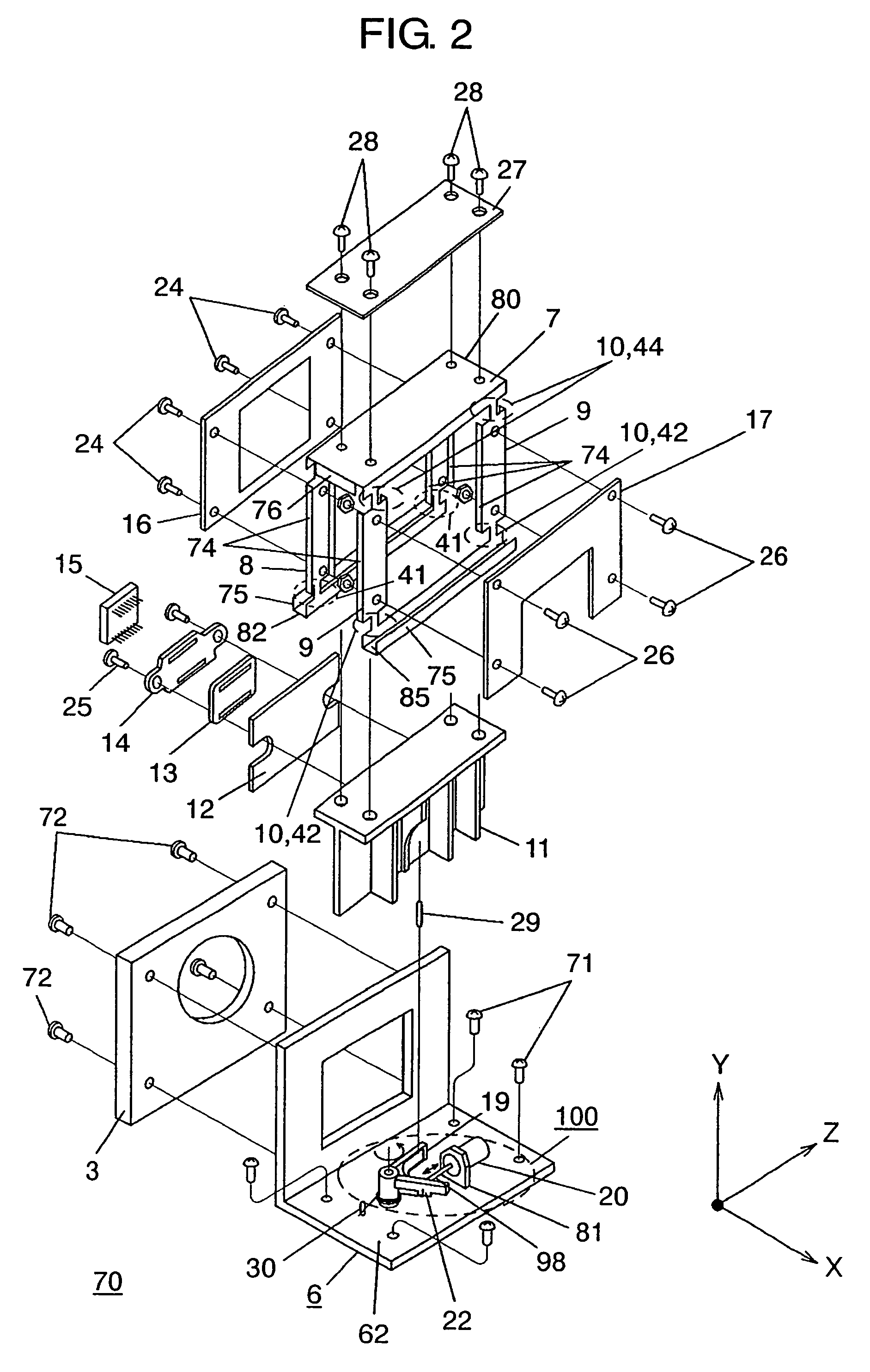
[0109]First, a configuration of photographing apparatus 1 according to an embodiment of the present invention will be described. FIG. 1 shows a configuration of photographing apparatus 1 according to the embodiment of the present invention. FIG. 2 is an exploded perspective view showing a configuration of pickup device driving apparatus 70 according to an embodiment of the present invention. For simplification of description, an X axis direction, a Y axis direction, and a Z axis direction perpendicular to one another are shown in the drawings. The X axis direction is an optical axial direction of a lens part, and the Y axis and Z axis direction are perpendicular to the optical axis direction.

[0110]As shown in FIGS. 1 and 2, photographing apparatus 1 according to the embodiment of the present invention includes lens mounting part 2 attached with lens part 101 (not shown in FIGS. 1 and 2), base attaching part 3 for connecting below-described base 6 to lens mounting part 2, DC motor pa...


PUM


Abstract

A pickup device driving apparatus includes a base of which the position is fixed with respect to a lens part, a movable part, a pickup device which is attached to the movable part in a state that a pickup surface is perpendicular to an optical axial direction, a first support part and a second support part which support the movable part, a first rotating part, a second rotating part, a third rotating part, and a fourth rotating part, and a driving part for driving the pickup device such that the position of the pickup device is changed relative to the lens part in a state that rotating center axes form vertexes of a parallelogram.

Description

[0001]THIS APPLICATION IS A U.S. NATIONAL PHASE APPLICATION OF PCT INTERNATIONAL APPLICATION NO. PCT / JP05 / 020998 DATED NOV. 16, 2005.TECHNICAL FIELD[0002]The present invention relates to a photographing apparatus such as a monitoring camera apparatus or a video camera apparatus, and more particularly, to a pickup device driving apparatus for moving a pickup device in an optical axial direction, a photographing apparatus using the same, and a monitoring camera apparatus.BACKGROUND ART[0003]First, a conventional photographing apparatus will be described. As an example of a photographing apparatus, a monitoring camera apparatus will be described.[0004]Recently, a technology related to various monitoring camera apparatuses has been suggested. In particular, in a monitoring camera apparatus for performing a monitoring operation day and night, a technology of disposing an infrared-light cut filter for selectively transmitting visible light and absorbing infrared light on the front surface...

Claims


Application Information

Patent Timeline
Patent Type & Authority Patents(United States)
IPC IPC(8): G03B17/00
CPCG03B11/00G03B15/00H04N5/332H04N5/2253H04N5/33G03B17/02H04N23/54H04N23/11H04N7/18H04N23/00
Inventor WADA, JOUJITAKAHASHI, SHOKICHIIIIZUMI, MASAOMIMIZUNO, MASAFUMI
Owner PANASONIC I PRO SENSING SOLUTIONS CO LTD
Why Eureka
Try Eureka