Lens driving device

A lens driving device and lens technology, applied in projection devices, printing devices, focusing devices, etc., can solve the problems affecting the sensing accuracy of the driving performance of the lens driving device and being subjected to magnetic interference, so as to avoid magnetic interference and improve sensing Accuracy, volume reduction effect

Pending Publication Date: 2019-07-02
HUIZHOU SAGETECH OPTRONICS CO LTD
View PDF0 Cites 0 Cited by
  • Summary
  • Abstract
  • Description
  • Claims
  • Application Information

AI Technical Summary

Problems solved by technology

However, the reduced volume of the lens driving device easily causes the driving magnet and the sensing magnet to be magnetically interfered with each other due to being too close together, which affects the driving performance and sensing accuracy of the lens driving device

Method used


Image

  • Lens driving device
  • Lens driving device
  • Lens driving device

Examples


Embodiment Construction

[0022] Hereinafter, the present invention will be described in detail through the embodiments. The following embodiments do not limit the invention described in the claims, and do not limit all combinations of features described in the embodiments to be essential to the solution of the invention.

[0023] In this specification, for the convenience of description, it is defined that the subject is located in front of the optical axis direction of the lens. Among the components involved below, the end / surface located in front of the optical axis direction is referred to as the front / front surface / upper / upper surface of the component, and the end / surface located behind the optical axis direction is referred to as the component’s Rear / rear surface / below / lower surface.

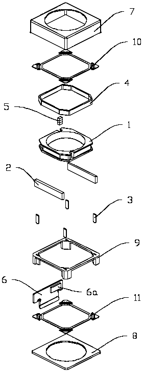
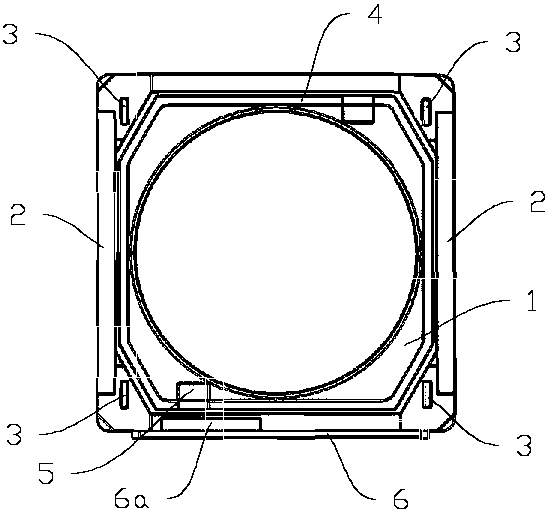
[0024] like Figure 1 to Figure 4 As shown, the first embodiment of the present invention mainly includes: a fixing part, a lens holder 1 , a driving coil 4 , a driving magnet 2 , a circuit board 6 , a sensing mag...


PUM


Abstract

The invention discloses a lens driving device, which comprises a lens holder, a fixing portion disposed on an outer circumference of the lens holder, a driving coil fixed to an outer side wall of thelens holder, a plurality of driving magnets fixed inside the fixing portion and opposed to the driving coil across the air, a spring element for supporting a movable portion suspension on the inner side of the fixing portion, a sensing element fixed to the inner side of the fixing portion, a sensing magnet fixed to the lens holder and opposed to the sensing element across the air, and at least onemagnetic conductive sheet with one arranged between the driving magnet closest to the sensing magnet and the sensing magnet. According to the lens driving device disclosed in the invention, the magnetic conductive sheets are arranged between the driving magnets and the sensing magnet, the magnetic field direction of the driving magnet is guided, magnetic interference between the driving magnet and the sensing magnet is thus avoided, the driving and sensing accuracy of the lens driving device is improved, and besides, the driving magnets and the sensing magnet can be set at a closer distance,which further reduces the volume of the lens driving device.

Description

technical field [0001] The invention relates to a lens driving device used in a camera installed in electronic products such as mobile phones. Background technique [0002] In recent years, portable electronic products such as smartphones, tablets and wearable devices equipped with small cameras have been widely popularized, and the cameras now have the function of auto focus. Autofocus is generally realized by driving the movement of the lens by a motor (lens driving device). The principle is to generate a Lorentz force on the electrified coil by driving a magnet, so that the lens moves in the direction of its optical axis. In order to focus accurately and quickly, the current lens driving device is equipped with a position detection device, which detects the location of the lens through a magnetic sensor and a sensing magnet, so that the movement of the lens can be controlled more precisely. With the increasing miniaturization of electronic products, the lens driving devi...

Claims


Application Information

Patent Timeline
Patent Type & Authority Applications(China)
IPC IPC(8): G02B7/10G03B13/34G03B30/00
CPCG02B7/10G03B13/34
Inventor 游证凯李育昇许乃文
Owner HUIZHOU SAGETECH OPTRONICS CO LTD
Why Eureka
Try Eureka