Voltage-controlled oscillator for multi-band and RF communication apparatus having the same

a voltage control and communication apparatus technology, applied in the direction of oscillator, pulse generator, pulse technique, etc., can solve the problems of reducing the rf communication apparatus, difficult continuous frequency tuning, and very limited tuning range, so as to prevent phase noise from deteriorating

Inactive Publication Date: 2009-12-01
SAMSUNG ELECTRONICS CO LTD
View PDF7 Cites 7 Cited by
  • Summary
  • Abstract
  • Description
  • Claims
  • Application Information

AI Technical Summary

Benefits of technology

[0012]Exemplary embodiments of the present invention provide a voltage-controlled oscillator (VCO) for a multi-band receiver, which can operate in a multi-frequency band while preventing phase noise from deteriorating in a high-frequency band, and a radio-frequency (RF) communication apparatus having the VCO.

Problems solved by technology

The range of tuning is very limited when using only the varactor, however, since the range of controlling the varactor is limited and active devices in the VCO have parasitic components.
The inductors occupy a larger chip area than the capacitors, however, and continuous frequency tuning is difficult when the inductors are used.
As the sizes of RF communication apparatuses have been reduced more and more, however, it is required to control a multi-band frequency signal with only a VCO, thus causing many problems.
In general, since a VCO that uses a fine tune branch has a fixed gain, it is difficult to control the gain of the VCO in a low frequency band and a high frequency band in different respective fashions.
For example, when a VCO for a low frequency band generates a high-frequency signal, since the VCO for a low frequency band needs a large gain, the gain of the high-frequency signal is unnecessarily increased, thus increasing phase noise.
Accordingly, an increase in the phase noise causes a serious problem.

Method used


Image

  • Voltage-controlled oscillator for multi-band and RF communication apparatus having the same
  • Voltage-controlled oscillator for multi-band and RF communication apparatus having the same
  • Voltage-controlled oscillator for multi-band and RF communication apparatus having the same

Examples


Embodiment Construction

[0025]Hereinafter, exemplary embodiments of the present invention will be described in detail with reference to the accompanying drawings. Like reference numerals denote like elements throughout the drawings.

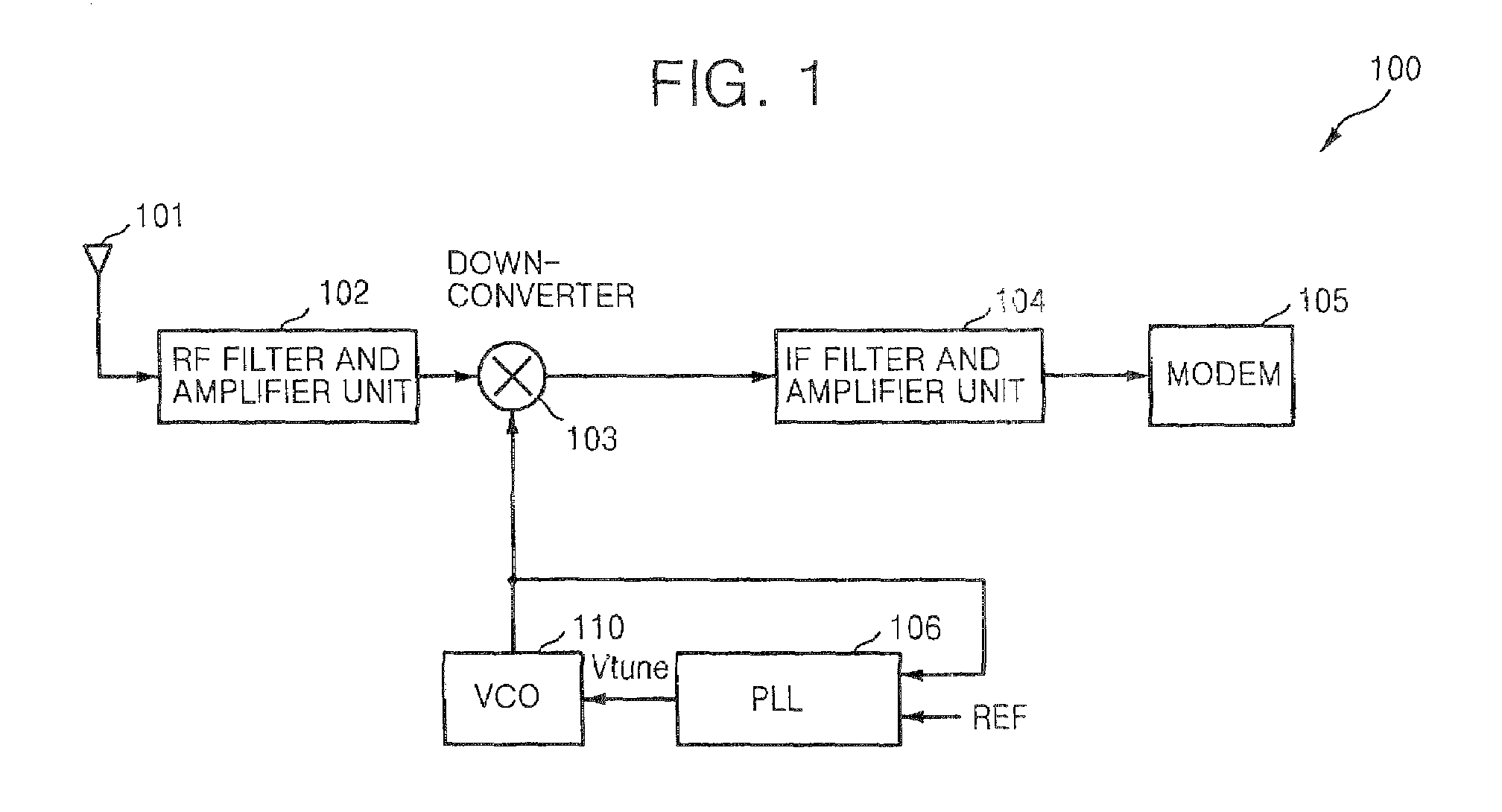
[0026]FIG. 1 is a block diagram of a radio-frequency (RF) communication apparatus 100 according to an exemplary embodiment of the present invention. In particular, FIG. 1 is a schematic block diagram of a receiver 100 of an RF communication apparatus, according to an exemplary embodiment of the present invention.

[0027]Referring to FIG. 1, the receiver 100 includes an antenna 101, an RF filter and amplifier unit 102, a down-converter 103, an intermediate-frequency (IF) filter and amplifier unit 104, a modem 105, a phase locked loop (PLL) 106, and a voltage-controlled oscillator (VCO) 110.

[0028]The RF filter and amplifier 102 receives incoming RF signals via the antenna 101, amplifies only the RF signal having a desired frequency band of the received RF signals, and outputs the am...


PUM


Abstract

A voltage-controlled oscillator (VCO) for a multi-band receiver, and a radio-frequency (RF) communication apparatus having the same. The VCO includes at least two fine tune branches, that is, a main fine tune branch and an auxiliary fine tune branch. The main fine tune branch includes at least one variable capacitor whose capacitance varies according to a tuning voltage. The auxiliary fine tune branch includes at least one varactor that operates either as a variable capacitor whose capacitance varies according to the tuning voltage or a fixed capacitor regardless of the tuning voltage, based on an operating frequency band. Accordingly, it is possible to prevent phase noise from increasing by varying the gain of the VCO according to the frequency band of an oscillation signal from the VCO.

Description

CROSS-REFERENCE TO RELATED PATENT APPLICATION[0001]This application claims the priority of Korean Patent Application No. 10-2006-0035030, filed on Apr. 18, 2006, in the Korean Intellectual Property Office, the disclosure of which is incorporated herein in its entirety by reference.BACKGROUND OF THE INVENTION[0002]1. Technical Field[0003]The present disclosure relates to a radio-frequency (RF) communication apparatus and more, particularly, to a multi-band voltage-controlled oscillator (VCO) whose gain can be controlled depending upon a frequency band of interest, and an RF communication apparatus having the same.[0004]2. Discussion of the Related Art[0005]A local oscillator is included in a radio-frequency (RF) communication apparatus for conversion of signal frequency. A representative example of the local oscillator is a voltage-controlled oscillator (VCO) capable of changing an oscillation frequency according to a control voltage.[0006]A large number of RF communication apparatus...

Claims


Application Information

Patent Timeline
Patent Type & Authority Patents(United States)
IPC IPC(8): H03K3/282
CPCH03B5/1228H03B5/1215H03B5/1293H03B5/1221H03B5/1243H03B5/08
Inventor YU, JIN-HYUCK
Owner SAMSUNG ELECTRONICS CO LTD
Why Eureka
Try Eureka