Method and apparatus for pneumatic excavation

a pneumatic and excavation technology, applied in mechanical machines/dredgers, liquid/gas jet drilling, construction, etc., can solve the problems of large tools and heavy weight, and achieve the effects of avoiding the risk of damage to underground cables, improving safety, and lightweigh

Inactive Publication Date: 2009-12-15
HURSEN THOMAS FRANCIS
View PDF8 Cites 5 Cited by
  • Summary
  • Abstract
  • Description
  • Claims
  • Application Information

AI Technical Summary

Benefits of technology

[0007]The present invention provides an improved, safe, lightweight, functionally optimized and economical supersonic excavator. The pneumatic excavator of the present invention provides the combination of one supersonic air digging or excavation nozzle and one vacuuming or evacuation nozzle which is also supersonic and is mechanically and dynamically coupled, and concentric with, and tandemly mounted about the same center line as the excavating nozzle. The pneumatic excavating tool of the present invention is supplied from a single plenum and powered by a single air source for safe tunneling, horizontal or v...

Problems solved by technology

In other instances the tools are very large and heavy and must therefore be mounted on a vehicle such as a truck or tracto...

Method used


Image

  • Method and apparatus for pneumatic excavation
  • Method and apparatus for pneumatic excavation
  • Method and apparatus for pneumatic excavation

Examples


Embodiment Construction

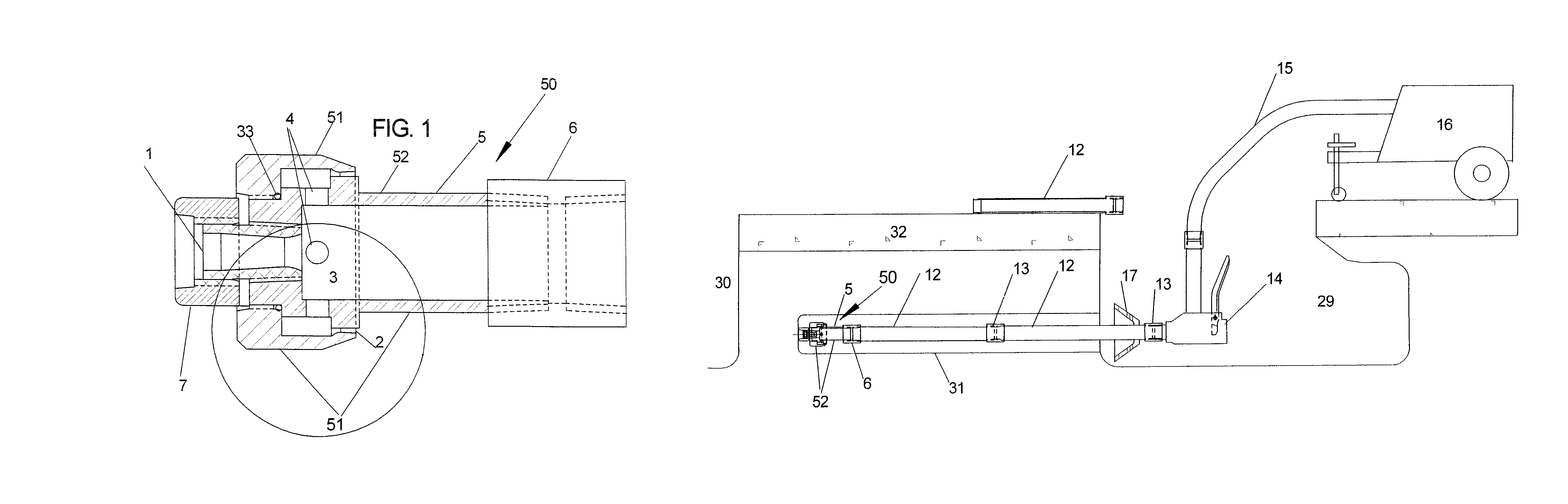
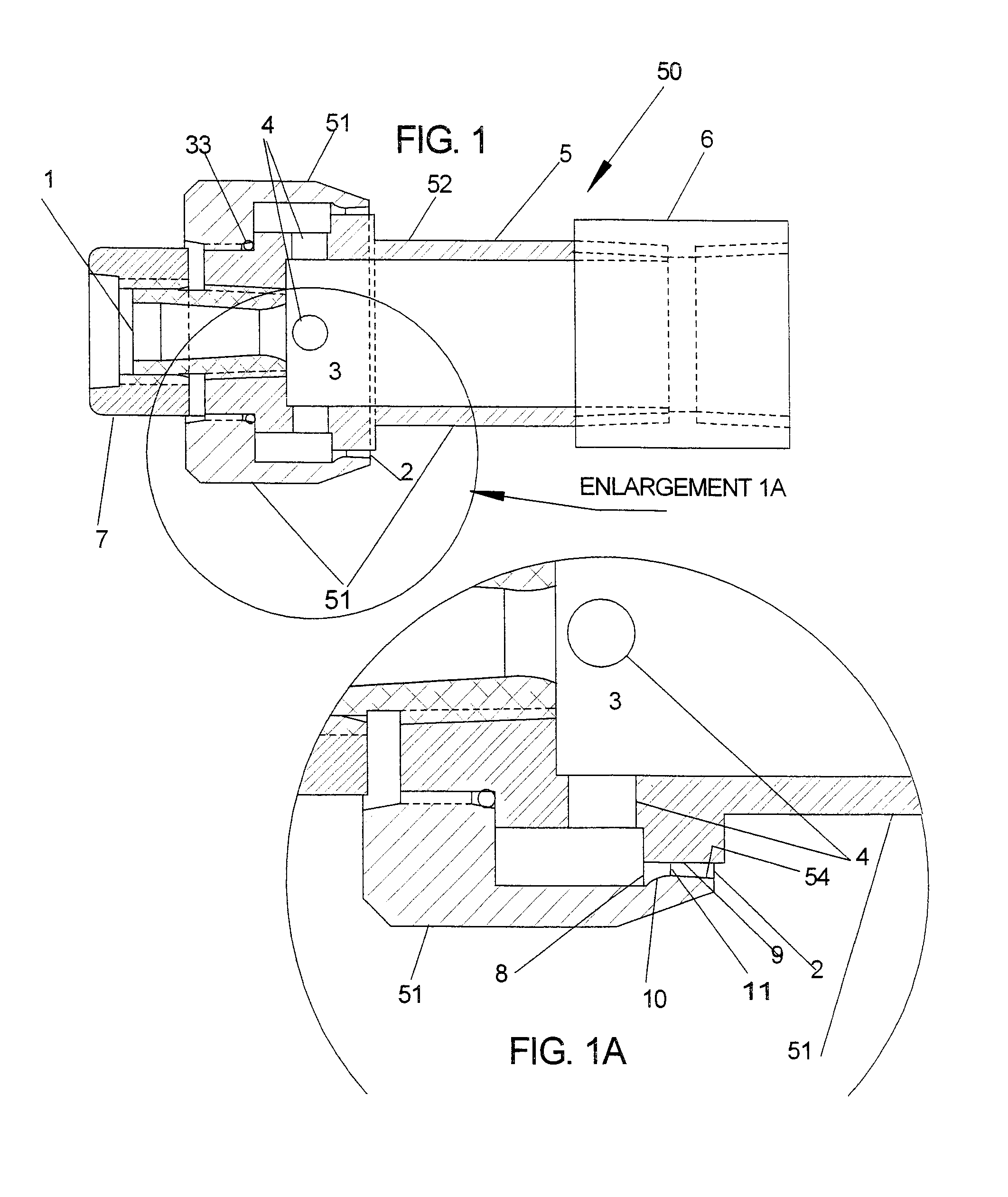
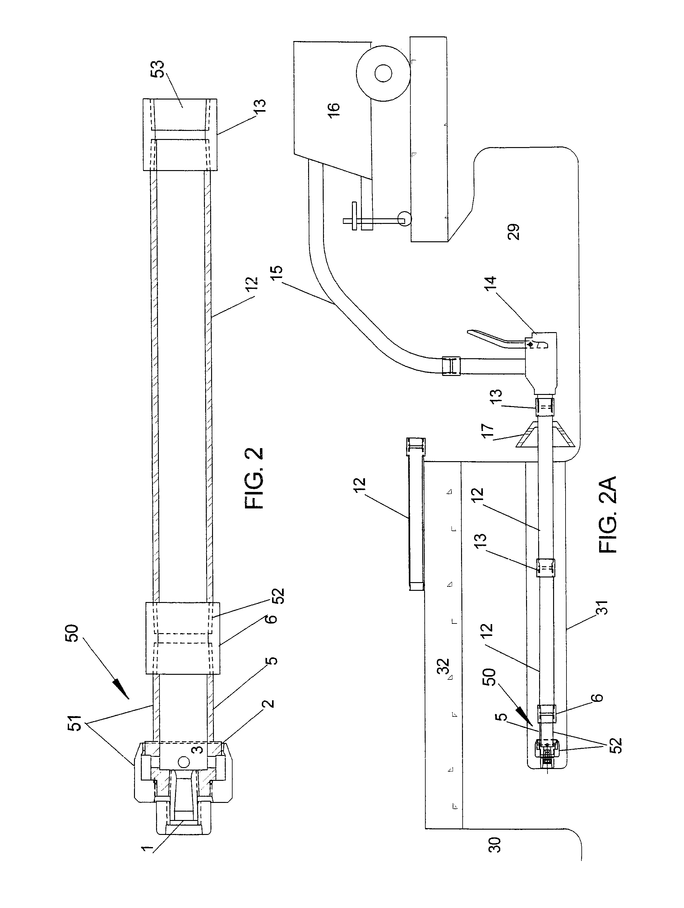
[0027]Referring to FIGS. 1 through 2A, the high pressure pneumatic device 50 of the present invention for excavating and removing material, such as earth, includes a pneumatic delivery tube comprised of rigid tube sections 5 and 12 coupled together as illustrated with couplings 6 and 13. Additional delivery tubes 12 may be added as desired and required. The pneumatic delivery tube (5, 6, 12, 13) is provided with a rearward proximal inlet 53 connected to a source of air under pressure in the form of air compressor 16 via flexible hose coupling 15 and single lever valve 14.

[0028]A nozzle housing 51 is provided on the distal outlet end 52 and is provided with a forwardly directed excavation nozzle 1 contoured and dimensioned for delivery of air under pressure therethrough at supersonic speeds for digging material or earth in front of it as illustrated in FIG. 2A. The nozzle housing 51 includes a rearwardly directed evacuation nozzle 2 also connected to the air under pressure supplied f...


PUM


Abstract

Material is pneumatically excavated and removed by discharging air under pressure from an excavation nozzle at supersonic speeds in a forward direction for excavating the material, and simultaneously discharging air under pressure from an evacuation nozzle also at supersonic speeds in a rearward direction at an adjacent position rearward of the point of forward discharge for assisting the removal of the excavated material in a rearward direction. The evacuation nozzle is in the form of a continuous annular air stream that is maintained concentric with the excavation nozzle. The nozzles are sized to provide maximum excavation and removal efficiency in co-relation to the PSI and the CFM output capabilities of the selected air source and the nozzles are positioned sufficiently close to each other whereby dynamic flow coupling is established between the nozzles such that material digging and removal performance and efficiency are maximized.

Description

CROSS REFERENCE TO RELATED APPLICATION[0001]This application claims the benefit of Provisional Application No. 60 / 845,821, filed Sep. 19, 2006, entitled “SAFE, SUPERSONIC AIR, HORIZONTAL EXCAVATOR”, which is hereby incorporated by reference in its entirety.BACKGROUND OF THE INVENTION[0002]This invention relates generally to excavation of soil, and more particularly to pneumatic excavation.[0003]Tools for locating and uncovering buried utilities and other buried objects, such as tree roots etc., safely and effectively, using supersonic air jets powered by commercial air compressors, and using one or more supersonic excavation nozzles, have been used in recent years. Supersonic is defined as any speed over the speed of sound (Mach1), which is approximately 761 mph. Also, air tools for vacuuming the soil from the excavation site, such soil having been previously crumbled by a supersonic air digger or other means, have also been in common use. Some of these pneumatic excavation tools ar...

Claims


Application Information

Patent Timeline
IPC IPC(8): E02F3/88
CPCE02F3/905E21B7/18E02F5/101E02F3/925
Inventor HURSEN, THOMAS FRANCIS
Owner HURSEN THOMAS FRANCIS
Why Eureka
Try Eureka