Wrist brace and method for alleviating and preventing wrist pain

a wrist brace and wrist technology, applied in the field of wrist braces, can solve problems such as compression of the ulnar nerve, and achieve the effect of preventing unwanted wrist tendons from stretching and increasing or decreasing the amount of focused pressur

Inactive Publication Date: 2009-12-29
NYI FRLIN H
View PDF22 Cites 33 Cited by
  • Summary
  • Abstract
  • Description
  • Claims
  • Application Information

AI Technical Summary

Benefits of technology

[0012]In general terms, the present invention is directed to a novel wrist brace construction that utilizes pressure transmitting members designed to impart localized and direct pressure on specific tendons that are more vulnerable to stretching and developing injury to the wrist. In this manner, the present invention is designed to help prevent the unwanted stretching of the wrist tendons along with the associated inflammation and discomfort associated with a wrist injury. The wrist brace includes a flexible main body which is adapted to be wrapped around the hand / wrist of the wearer. Pressure transmitting members are disposed along the main body of the wrist brace at particular locations where the pressure transmitting members will be strategically placed over the tendons of interest once the wrist brace is placed around the wrist of the wearer. In one aspect of the invention, the flexible main body can be snuggly wrapped around the user's hand / wrist to allow the pressure transmitting members to impart localized and focused pressure on specific tendons of interest. The size and shape of these pressure transmitting members are selected such that the pressure transmitting member applies most of the focused pressure on the tendon itself while only a small amount of focused pressure will be actually be applied in the area surrounding the tendon. In one aspect of the present invention, the flexible main body includes means for varying the amount of focused pressure which can be developed by the pressure transmitting members. For example, a hook and loop fastener (i.e. Velcro fastener) can be used to allow the wearer to change the amount of inward pressure developed by the wrist brace and the pressure transmitting members. Such an element allows the wearer to increase or decrease the amount of focused pressure developed by simply positioning the loop fastener to vary the snugness that the flexible main body impart to the wearer's hand / wrist.
[0013]In one aspect of the invention, the pressure transmitting member is designed to provide localized and focused pressure directly onto the flexor tendons which extend through the carpal tunnel. These flexor tendons includes the flexor digitorum superficialis tendons and flexor digitorum profundus tendons. The pressure transmitting member is disposed on the flexible main body of the wrist brace and is adapted to apply the focused pressure to the flexor tendons in the region of the transverse carpal ligament, which forms part of the carpal tunnel. In this regard, the pressure transmitting member provides sufficient amount of radial force or focused pressure on these particular tendons to prevent them from stretching outwardly during physical activity. As a result, normal trauma and stretching that usually occurs during physical activity are diminished since the pressure transmitting member helps to maintain these tendons from stretching outwardly, thus helping to prevent the tendons from becoming swollen or inflamed. This same pressure transmitting member also will apply focused pressure to the palmaris longus tendon since this tendon lies directly over the flexor tendons above the transverse carpal ligament and should help to prevent inflammation or swelling of this tendon as well.
[0014]In another aspect of the invention, additional pressure transmitting members are disposed on the flexible main body forming the wrist brace to apply focused pressure on other tendons in the wrist, such as the flexor carpi radialis tendon, which extends outside of the carpal tunnel but is none the less susceptible to the same outward stretching that can cause swelling and inflammation of this tendon as well. Another pressure transmitting member can be disposed on the flexible main body forming the wrist brace to apply focused pressure on the flexor carpi ulnaris tendon in order to help prevent ulnar neuritis from developing in the wrist. Although the flexor carpi ulnaris tendon is not located directly in Guyon's canal, the swelling or inflammation of this tendon can lead to compression of the ulnar nerve which is the cause of ulnar neuritis. Prevention of the swelling of this particular tendon can reduce pressure to be placed on the ulnar nerve.
[0015]The present invention also utilizes a pressure transmitting member disposed on the main body to apply focused pressure to the tendons on the backside of the wrist, which are also susceptible to stretching that can cause inflammation and pain. This pressure transmitting member is designed to extend over and apply focused pressure to the extensor digitorum tendons and the extensor indicis tendon along the region of the extensor retinaculum ligament. This pressure transmitting member should help to prevent the unwanted stretching of these tendons during physical activity.
[0016]The wrist brace of the present invention is designed to allow the wearer to maintain almost full use of his / her fingers, along with near normal flexion and extension of the wrist, while the wrist brace is being worn. As a result, the wearer can assume normal activities with his / her hand while preventing tendons from becoming swollen or inflamed even if when performing repetitive hand / wrist motions which would otherwise result in such swelling and inflammation. A wrist brace in accordance with the present invention is thus useful in alleviating the wrist pain associated with wrist injuries, including, but not limited to carpal tunnel syndrome and ulnar neuritis since the wrist brace helps to present the stretching of the tendons which is the primary cause of the wrist injury in the first place. As a result, the use of the wrist brace, in conjunction with another non-surgical treatment, such as taking anti-inflammatory drugs, will greatly diminish the pain and discomfort associated with wrist injuries. Additionally, the wrist brace of the present invention can be used before the onset of any wrist injury or pain. An individual can wear the wrist brace when performing repetitive hand motions or engaging in other activities which would otherwise lead to wrist injury since there is little loss of normal motion of the wrist and fingers when wearing the present invention.

Problems solved by technology

Although the flexor carpi ulnaris tendon is not located directly in Guyon's canal, the swelling or inflammation of this tendon can lead to compression of the ulnar nerve which is the cause of ulnar neuritis.

Method used


Image

  • Wrist brace and method for alleviating and preventing wrist pain
  • Wrist brace and method for alleviating and preventing wrist pain
  • Wrist brace and method for alleviating and preventing wrist pain

Examples


Embodiment Construction

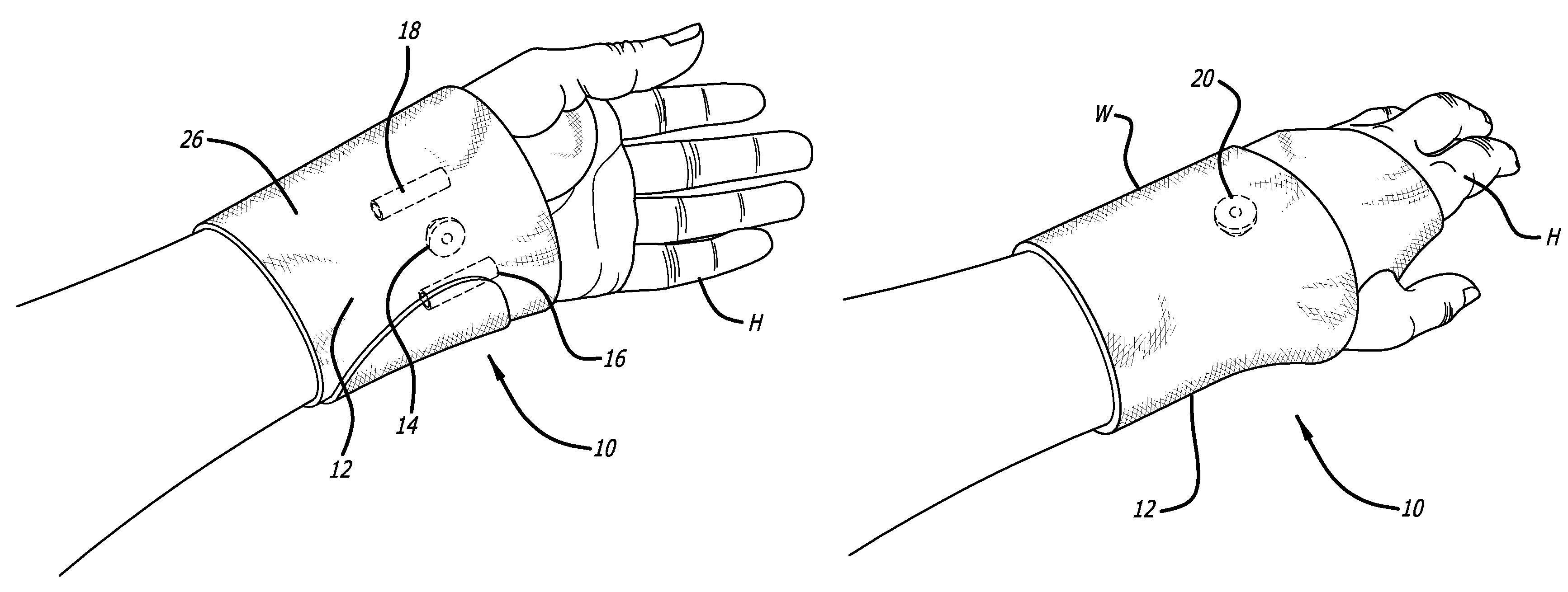
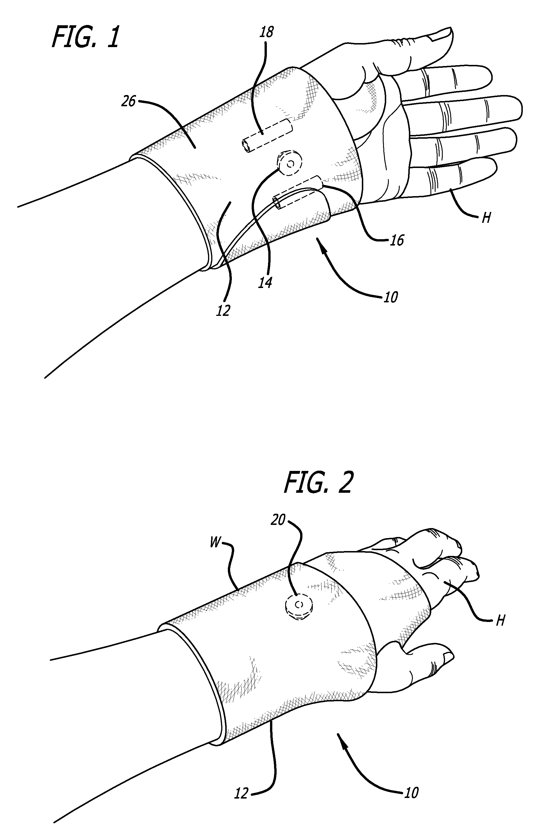
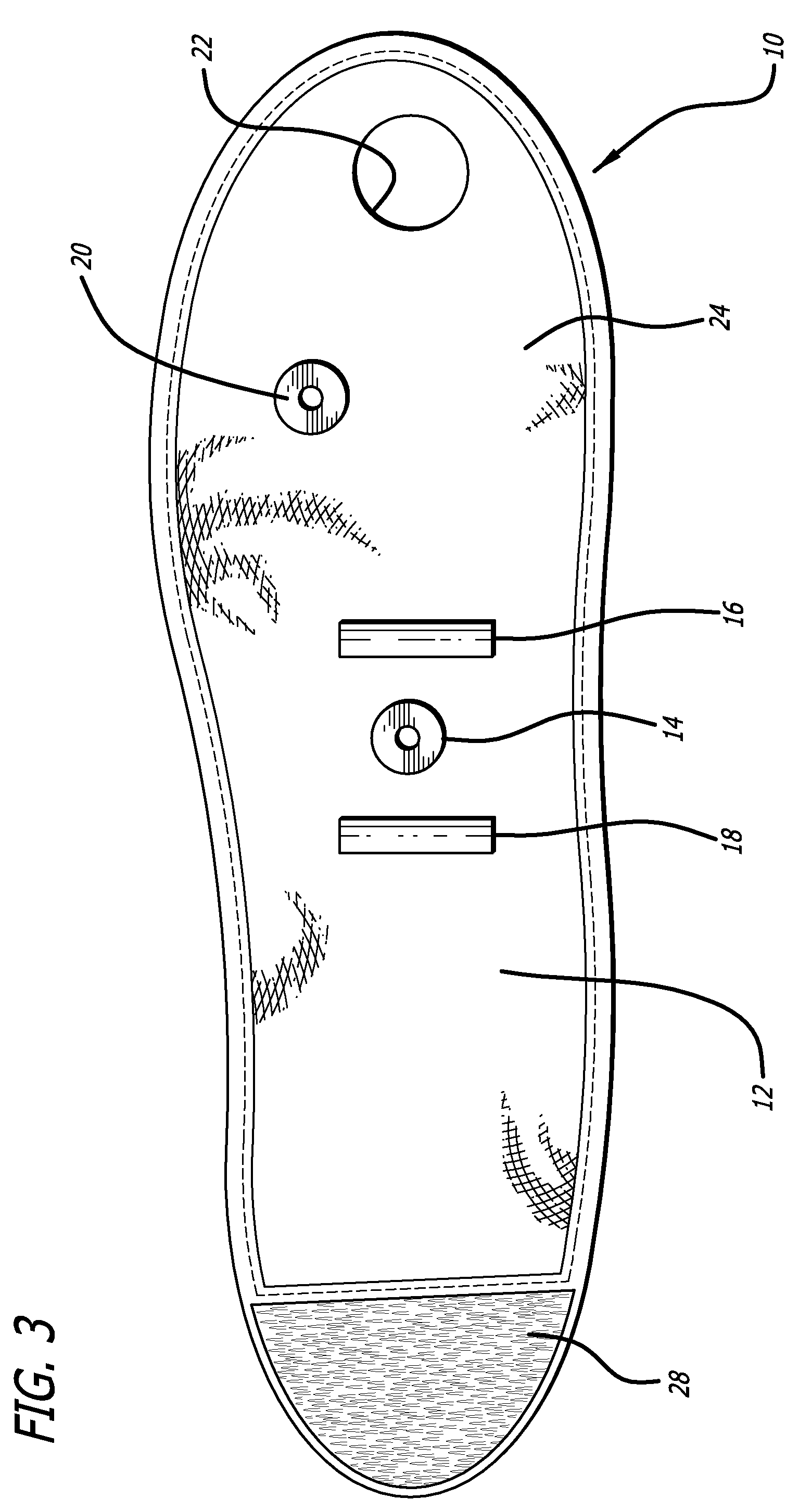
[0028]Referring now to FIGS. 1-6, an embodiment of a wrist brace made in accordance with the present invention is generally designated by the reference numeral 10. The wrist brace 10 includes a flexible main body 12 that is designed to wrap around the hand (H) / wrist(W) of the wearer. The wrist brace 10 includes pressure transmitting members 14-20 which are disposed on the flexible main body 12 and are adapted to apply localized and focused pressure to certain tendons in the wrist. The identification of these tendons and the anatomy of the wrist will be addressed in greater detail below. The particular construction of the particular wrist brace 10 shown in FIGS. 1-6 allows the wrist brace 10 to be worn on either the left or right wrist of the wearer.

[0029]Referring specifically now to FIG. 3, the flexible main body 12 is shown as an elongate structure having a thumb opening 22 formed therein. This flexible main body 12 includes an inner surface 24, shown in FIG. 3, and an outer surfa...


PUM


Abstract

A wrist brace includes a flexible main body having one or more pressure transmitting members disposed thereon designed to impart focused pressure on a tendon of interest.

Description

BACKGROUND OF THE INVENTION[0001]The present invention relates generally to wrist braces, and more particularly, to a flexible wrist brace for alleviating the symptoms associated with wrist injuries, such as carpal tunnel syndrome and ulnar neuritis, without restricting the wearer's ability to grasp objects and perform daily tasks. Additionally, the present invention is directed to methods for alleviating and preventing wrist pain associated with such wrist injuries.[0002]Many people suffer from injury to the soft tissues of the wrist and carpal tunnel, often caused by frequent, sustained repetitive motion involving the hands. Repetitive activities which require the same or similar hand / wrist action can result in injuries which have been collectively referred to as Cumulative Repetitive Stress Syndrome or Repetitive Strain Injury. The most familiar and common of such wrist injuries is known as carpal tunnel syndrome which produces pain, discomfort, nerve conduction disturbances, and...

Claims


Application Information

Patent Timeline
Patent Type & Authority Patents(United States)
IPC IPC(8): A61F5/00A61F13/00
CPCA61F5/30A61F5/0118
Inventor NYI, FRANKLIN H.
Owner NYI FRLIN H
Why Eureka
Try Eureka