Mammographic apparatus, breast compression plate, and breast fixing method

a technology of breast compression and mammography, which is applied in the field of mammography apparatus, breast compression plate, and breast fixing method, can solve the problems of breast to be displaced in position, and breast to be positioned in position, so as to reduce the number of assistive actions to position the breast, and the effect of easily and accurately positioning the breas

Active Publication Date: 2009-12-29
FUJIFILM CORP
View PDF11 Cites 6 Cited by
  • Summary
  • Abstract
  • Description
  • Claims
  • Application Information

AI Technical Summary

Benefits of technology

[0018]It is a general object of the present invention to provide a mammographic apparatus, a breast compression plate, and a breast fixing method which are capable of positioning a breast easily and accurately in an appropriate position while reducing assistive actions to position the breast.
[0019]A major object of the present invention is to provide a mammographic apparatus, a breast compression plate, and a breast fixing method which are capable of positioning a breast accurately in an appropriate position regardless of an image capturing process that is employed.
[0020]Another object of the present invention is to provide a mammographic apparatus, a breast compression plate, and a breast fixing method which are capable of positioning a portion of a breast near the nipple thereof highly accurately.
[0021]Still another object of the present invention is to provide a mammographic apparatus, a breast compression plate, and a breast fixing method which allow the operator to remove a hand thereof easily from a position to hold a breast after having positioning the breast.

Problems solved by technology

Therefore, after having pressed the breast compression plate against the breast, the operator finds it difficult to remove the hand, and may cause the breast to be displaced in position when removing the hand.
However, as the portion of the breast near the nipple is not held by the breast compression plate in the initial phase of the breast compressing process, the portion of the breast near the nipple may possibly be displaced in position in the image capturing session.
As a result, the breast 3 is not positioned in an appropriate image capturing position.
Even if the operator holds and positions the breast with a hand, since the operator has to remove the hand at the time the breast compression plate approaches the image capturing base, the breast is liable to be displaced in position at this time.

Method used


Image

  • Mammographic apparatus, breast compression plate, and breast fixing method
  • Mammographic apparatus, breast compression plate, and breast fixing method
  • Mammographic apparatus, breast compression plate, and breast fixing method

Examples


Embodiment Construction

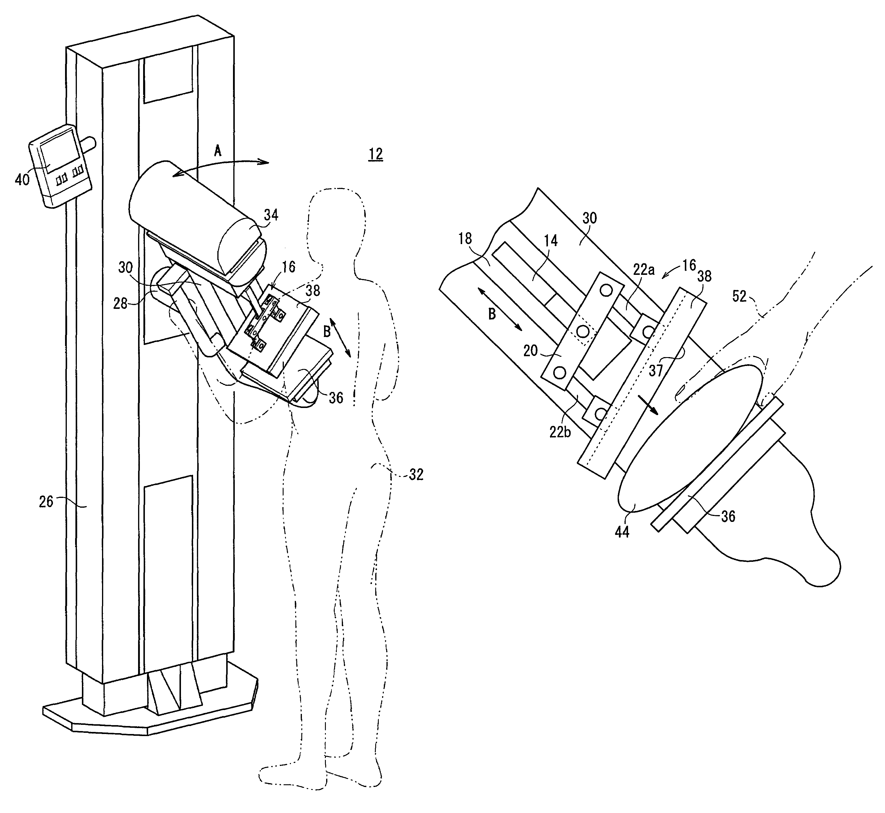
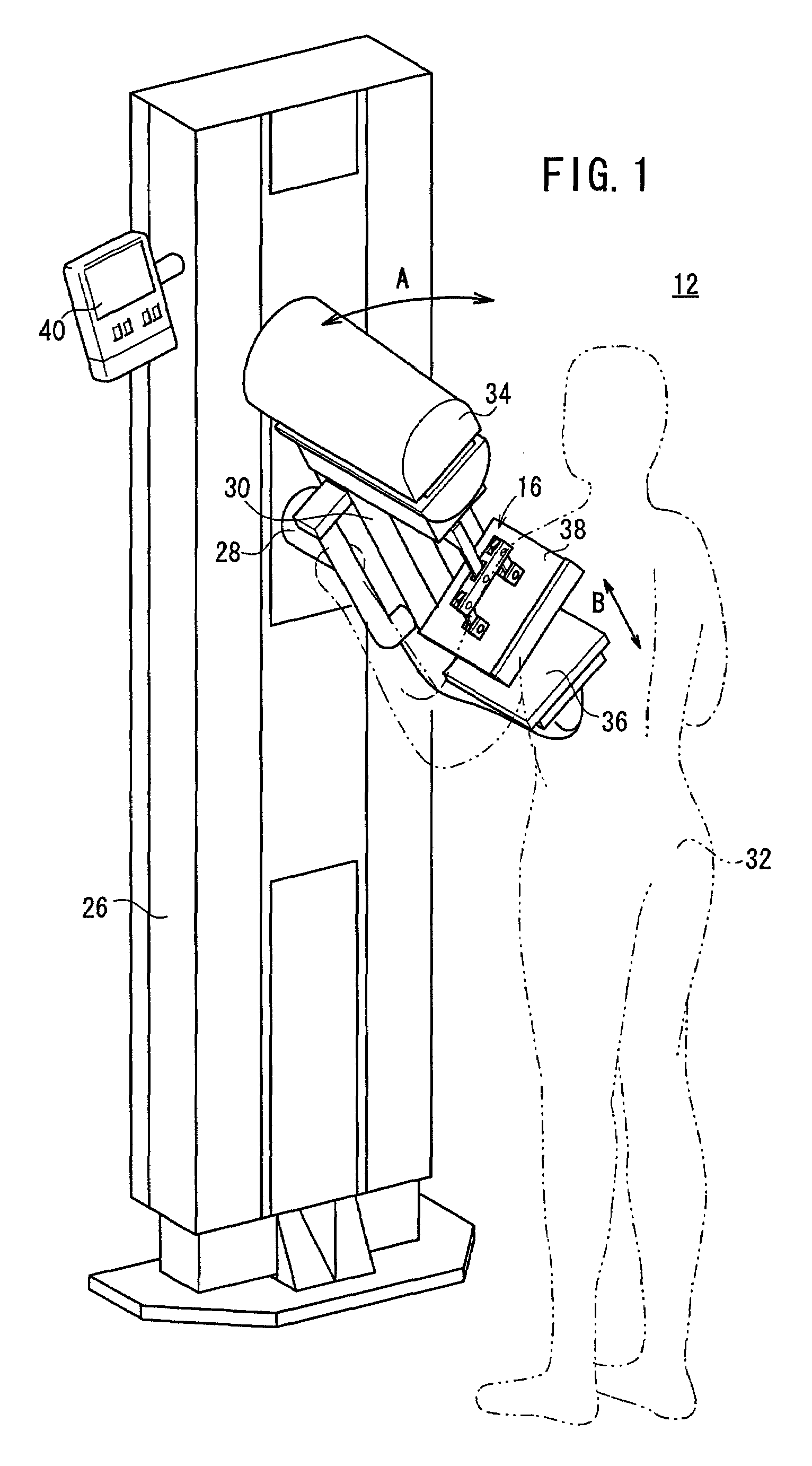
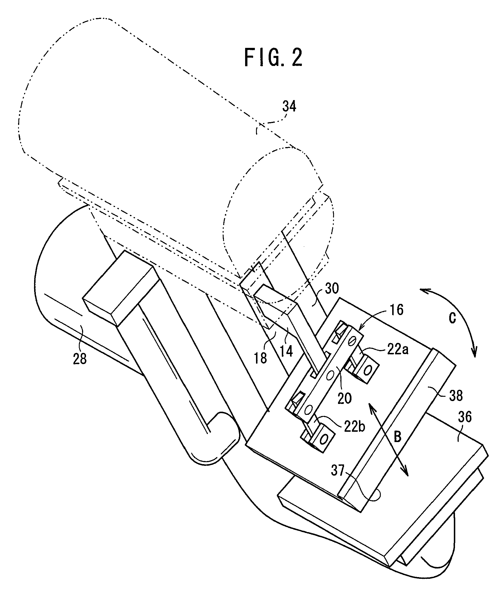
[0040]FIG. 1 shows in perspective a mammographic apparatus 12 according to an embodiment of the present invention, the mammographic apparatus 12 incorporating a breast compression plate and a breast fixing method according to the present invention.

[0041]As shown in FIG. 1, the mammographic apparatus 12 includes an upstanding base 26, a vertical arm 30 fixed to a horizontal swing shaft 28 disposed substantially centrally on the base 26, a radiation source housing unit 34 housing a radiation source for applying a radiation to a breast 44 (see FIG. 3) to be imaged of a subject 32 and fixed to an upper end of the arm 30, an image capturing base 36 housing a solid-state detector for detecting a radiation that has passed through the breast 44 to acquire radiation image information of the breast 44 and fixed to a lower end of the arm 30, and a breast compression plate 38 for pressing and holding the breast 44 against the image capturing base 36.

[0042]To the base 26, there is connected a di...


PUM


Abstract

A mammographic apparatus is set to take a medio-lateral oblique view (MLO) of a breast with an arm being tilted. After having positioned the breast on an image capturing base, the radiological technician moves a breast compression plate, which is tilted with respect to the image capturing base, toward the image capturing base. When the breast compression plate abuts against the breast and the breast is braced from below by the image capturing base, the radiological technician removes a hand from between the image capturing base and the breast compression plate, and then further moves the breast compression plate toward the image capturing base. A compression plate support mechanism turns the breast compression plate to make it substantial parallel to the image capturing base, thereby positioning the breast.

Description

BACKGROUND OF THE INVENTION[0001]1. Field of the Invention[0002]The present invention relates to a mammographic apparatus of capturing radiation image information of a breast, and a breast compression plate for compressing a breast and a breast fixing method for fixing a breast when an image of the breast is captured by the mammographic apparatus.[0003]2. Description of the Related Art[0004]In the medical field, there have widely been used radiation image capturing apparatus for applying a radiation emitted from a radiation source to a subject, and guiding the radiation that has passed through the subject to a solid-state detector or a stimulable phosphor panel, thereby recording radiation image information of the subject.[0005]The solid-state detector includes a solid-state detecting unit which comprises a matrix of charge collecting electrodes formed on an insulating substrate and a radiation conductor disposed on the charge collecting electrodes for generating electric charges de...

Claims


Application Information

Patent Timeline
Patent Type & Authority Patents(United States)
IPC IPC(8): A61B6/04
CPCA61B6/502A61B6/0414A61B6/54
Inventor KASHIWAGI, NOBUHIKO
Owner FUJIFILM CORP
Why Eureka
Try Eureka