Spread illuminating apparatus

a technology of illumination apparatus and illumination lamp, which is applied in the direction of lighting and heating apparatus, lighting support devices, instruments, etc., can solve the problems of difficult to achieve a backlight suitable for pseudo impulse driving, insufficient sized and shaped areas which are allowed to be area controlled, and low photoelectric conversion efficiency, etc., to achieve high image quality, low cost, and high performance

Inactive Publication Date: 2010-02-02
MINEBEAMITSUMI INC
View PDF5 Cites 11 Cited by
  • Summary
  • Abstract
  • Description
  • Claims
  • Application Information

AI Technical Summary

Benefits of technology

[0022]In the spread illuminating apparatus according to the present invention, the lighting units adapted to turn on and off individually in a controlled manner are arranged in a two dimensional manner, whereby the entire luminous region of the spread illuminating apparatus is divided into segment areas each of which is constituted by the light emitting surface area of each lighting unit, thus easily allowing a partial control of turning on and off the luminous region of the spread illuminating apparatus. In this connection, if the light emitting areas of the lighting units are appropriately shaped and sized and also if the lighting units are appropriately arranged according to the shape and size, then the segment areas which can be turned on and off individually in a controlled manner can be flexibly arranged, and consequently the spread illuminating apparatus can be preferably used as a backlight of an LCD device incorporating an area control driving method.
[0044]In the spread illuminating structured as described above according to the present invention, the entire luminous region is divided into a plurality of segment areas, at each of which light can easily be independently turned on and off in a controlled manner with its emission direction individually set. Consequently, the spread illuminating apparatus is suitable for use as a backlight of a multiple view LCD device of high image quality and high performance, in which a pseudo impulse driving method and an area control driving method are employed. And, with the spread illuminating apparatus according to the present invention, even a low cost LCD panel can constitute an LCD television featuring high brightness and contrast.

Problems solved by technology

Conventional backlights, however, have the following difficulties in keeping up with the aforementioned improvement of image quality and enhancement of performance.
In a direct light type backlight with CCFLs, since a CCFL has a low response speed, and since the number of CCFLs provided in a backlight is usually restricted, commonly it is difficult to achieve a backlight to suitably match a pseudo impulse driving (especially, the above-described black insertion driving method).
Also, in a direct light type backlight with CCFLs, the luminous region cannot be divided into individual areas in the direction orthogonal to the length of the CCFLs because of its structure, and therefore the areas which are allowed to be area-controlled are forced to be very inadequately sized and shaped.
However, the photoelectric conversion efficiency is low in achieving a white light by mixing lights from red, green and blue LEDs, thus raising problems with power consumption, heat value from light sources, cost, and the like for achieving a white light with an adequate brightness.
If such a backlight is used in a multiple view LCD device which has a display mode that multiple different picture images are displayed in a plurality of different directions, then the view angle characteristic of the backlight does not fit the display mode of the multiple view LCD device described above, and consequently the brightness characteristic proper to the backlight cannot be fully utilized thus inviting brightness deterioration of the LCD device.
And, this brightness deterioration in the conventional backlight must usually be compensated for by increasing electric power inputted to the backlight, thus increasing power consumption.

Method used


Image

  • Spread illuminating apparatus
  • Spread illuminating apparatus
  • Spread illuminating apparatus

Examples


Embodiment Construction

[0050]An exemplary embodiment of the present invention will be described with reference to the accompanying drawings.

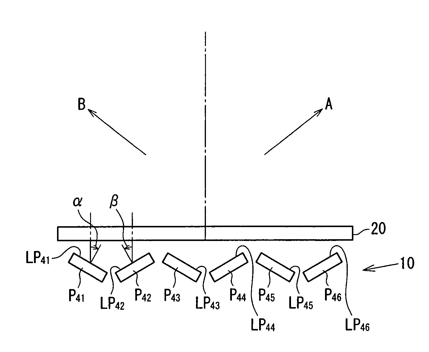
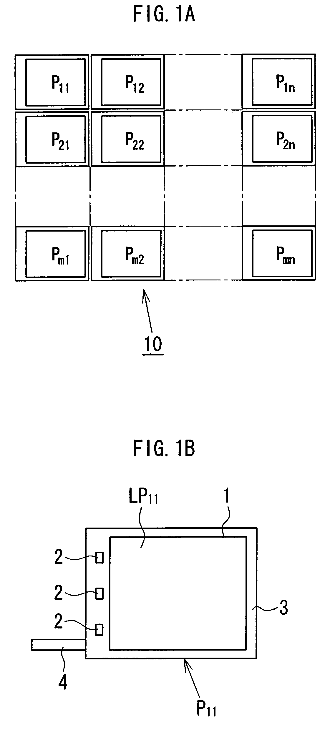
[0051]Referring to FIG. 1A, a spread illuminating apparatus 10 according to an embodiment of the present invention includes a plurality (m×n pieces in the figure) of lighting units P11 to Pmn arranged two dimensionally (in a matrix with m rows and n columns). The lighting units P11 to Pmn are of an edge light type and each principally include a light conductor plate 1 and LEDs 2 as light sources disposed at one side of the light conductor plate 1 as illustrated in FIG. 1B showing one lighting unit P11 as an example. In this connection, m and n may be natural numbers equal to 2 and larger and a detailed description of configuration examples will be made hereinafter.

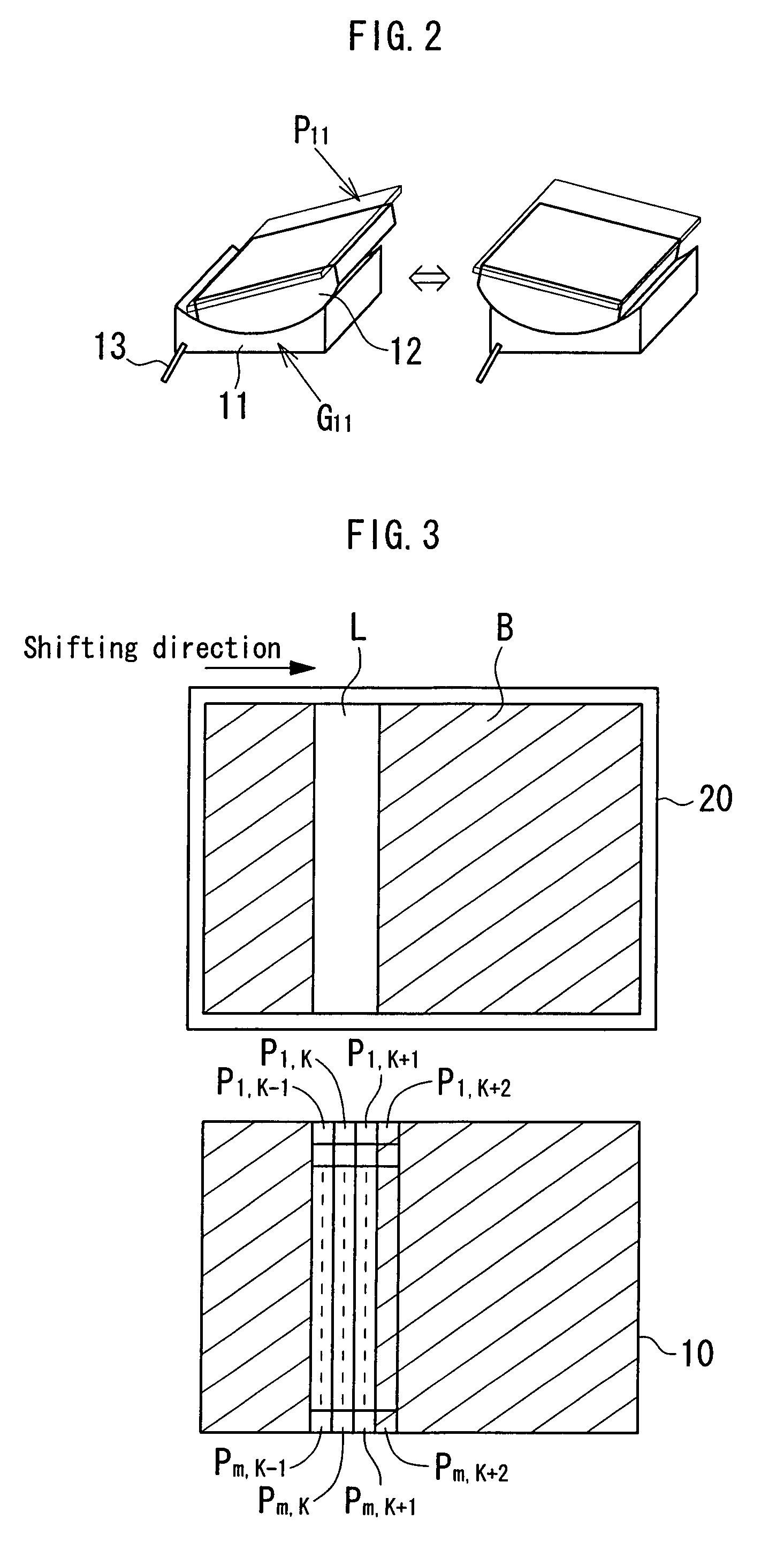
[0052]The light conductor plate 1 is a rectangular plate formed of a transparent resin material. Acrylic resin, polycarbonate resin and amorphous polyolefin are well balanced in terms of moldability and opti...


PUM


Abstract

A spread illuminating apparatus includes a plurality (m×n pieces) of lighting units (P11 to Pmn) which are disposed in a matrix with m rows and n columns, and each of which is an edge light type principally including a light conductor plate and at least one LED disposed at one side of the light conductor plate, and the entire luminous region of the spread illuminating apparatus is divided into segment areas constituted respectively by the lighting units (P11 to Pmn) which can be turned on and off in a controlled manner independently of one another.

Description

BACKGROUND OF THE INVENTION[0001]1. Field of the Invention[0002]The present invention relates to a spread illuminating apparatus suitable for use as a backlight unit for a liquid crystal display device.[0003]2. Description of the Related Art[0004]A liquid crystal display (LCD) device is extensively used as a display device for electronic appliances, and the like, and recently is increasingly replacing a cathode ray tube (CRT) also in a relatively large display device for such as a personal computer and a television set. For such a large LCD device, a direct light type backlight has been conventionally predominant which is structured such that a plurality of cold cathode lamps (hereinafter referred to as CCFLs as appropriate) as light sources are disposed immediately beneath an LCD panel, and in which light is condensed by an optical sheet and light intensity is uniformed by a diffuser sheet (refer to, for example, Japanese Patent No. 3653274).[0005]In many of such direct light type ...

Claims


Application Information

Patent Timeline
Patent Type & Authority Patents(United States)
IPC IPC(8): F21S4/00F21V21/00
CPCF21V21/30G02F1/133603Y10S362/80
Inventor KITAMURA, ATSUSHIADACHI, SHIGEYUKI
Owner MINEBEAMITSUMI INC
Why Eureka
Try Eureka