Remote controller device and method for hand operation of floor-mounted audio effects processors

Inactive Publication Date: 2010-03-09
GOLDEN MARY ELIZABETH
View PDF11 Cites 3 Cited by
  • Summary
  • Abstract
  • Description
  • Claims
  • Application Information

AI Technical Summary

Problems solved by technology

It should be noted that, other than the differences in the type of effect available, the size / shape of the housing, and the number of rotary potentiometers, used to vary the audio effects, the basic configuration of these devices has remained virtually unchanged in the forty years since their introduction, and though a multitude of floor-mounted effects devices are now used world wide, several inadequacies are inherent in their operation:1) Control over the devices is limited to the foot-operated on / off switch which only engages a pre-set effect to an audio signal.
)2) Being floor-mounted, access the manual controls (rotary potentiometers) is unavailable during normal use without the user stooping or crouching down.
(This is often unpractical as the user is usually required to maintain a standing or sitting position in order to play his / her instrument, sing at a stand-mounted microphone, or more frequently, both.
)3) In order to make any adjustment to the manual controls, the user must either:a) Make any adjustments prior to each song / piece and hope the adjustment was accurate (This is inherently difficult due to the need of an audio signal as well as the exact tempo of the song / performance in order to make adjustments that are often measured in milliseconds.
There are however, several inefficiencies in the currently marketed device:1) Unnecessarily complicated / costly design.2) Takes up extra floor space during performances / use.3) Due to its shorter drive shaft, the currently marketed device can only function when placed directly next to an effects pedal:If the user wishes to use the currently marketed device with an elongated effects processor (commonly known as a pedalboad) he / she is limited to those pedalboards having their control knobs located on either the extreme right or left hand side.Note that many pedalboards are equipped with see-saw type foot levers on one or both sides and are thus restricted from use with the currently marketed device.4) The currently marketed device is capable of controlling only one rotary potentiometer at a time.Even a two-channel version of this device would be too bulky and cost prohibitive to be practical.5) Guitar players are used to making adjustments to control knobs with their hands not their feet.
When trying to make fast, precise adjustments in increments that are often measured in milliseconds, replacing the control knob with yet another foot-operated apparatus does not efficiently, much less naturally solve the problem, it merely reconfigures it.

Method used


Image

  • Remote controller device and method for hand operation of floor-mounted audio effects processors
  • Remote controller device and method for hand operation of floor-mounted audio effects processors
  • Remote controller device and method for hand operation of floor-mounted audio effects processors

Examples


embodiment

Preferred Embodiment

[0062]Operation—FIGS 3 through 4F

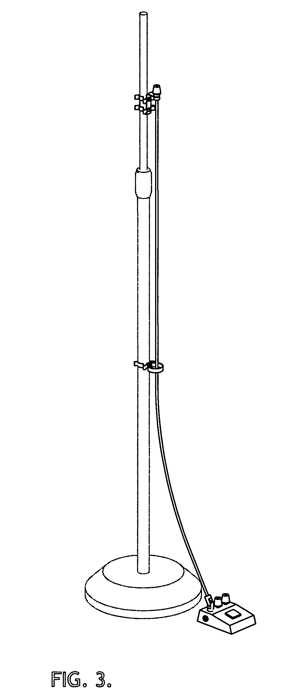
[0063]FIG. 3 shows device in operating position.

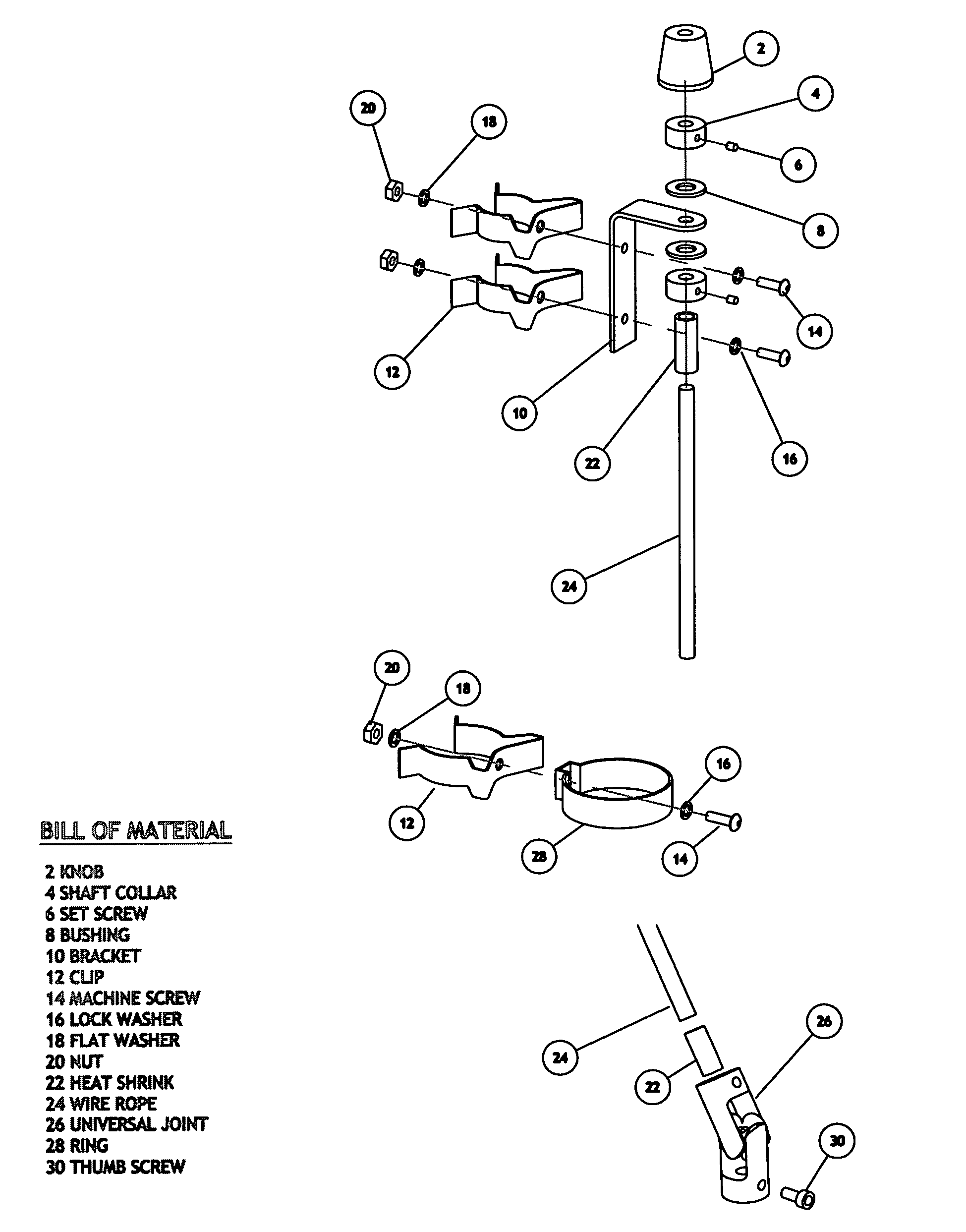
[0064]The control unit is first clipped to a microphone stand approximately 91.44 cm from the floor (FIG. 4A). The bottom end of the cable is then passed through the loom assembly (FIG. 4B), which is similarly clipped approximately 30 cm below the control unit (FIG. 4C).

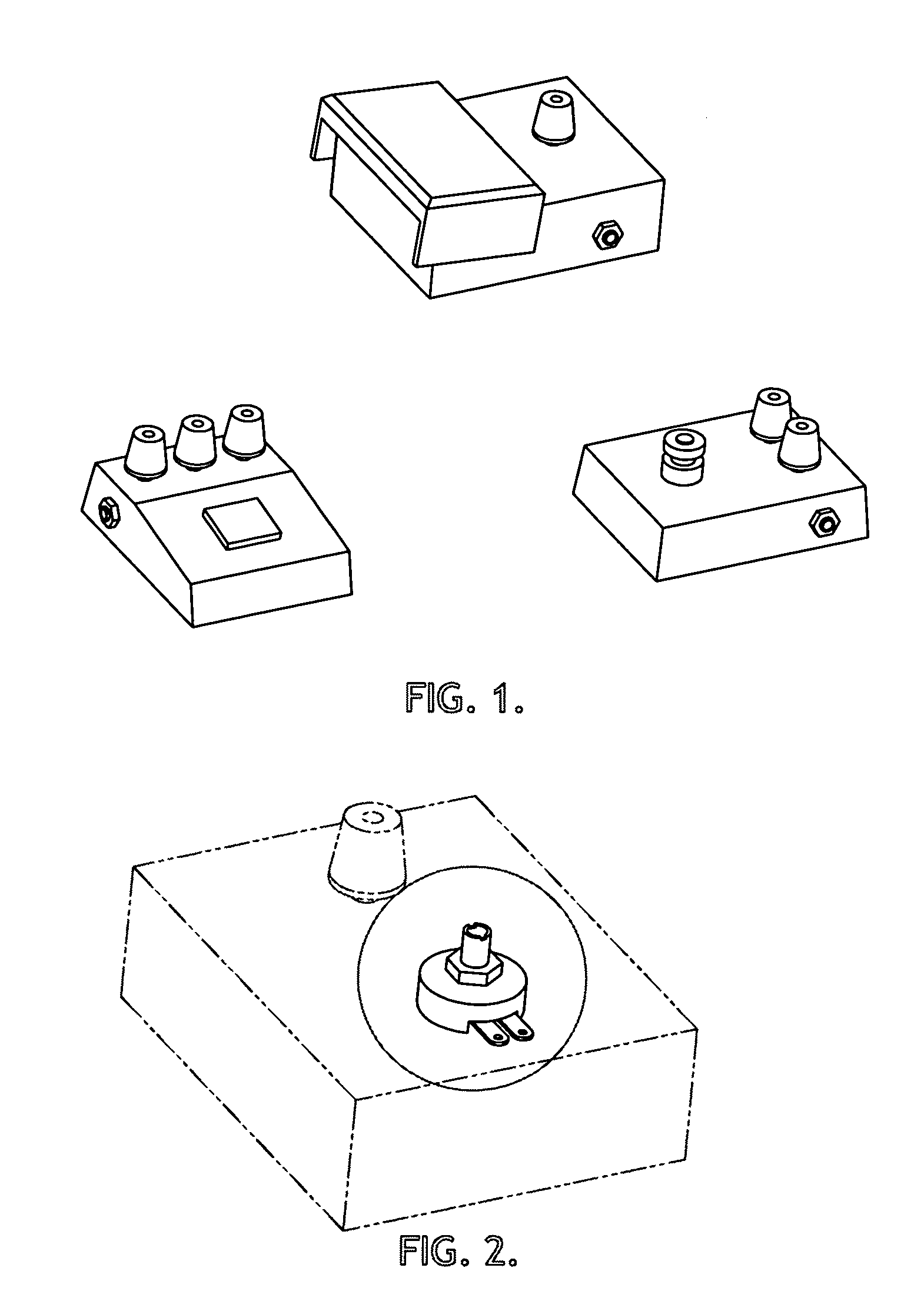
[0065]The user then removes from his / her effects device the knob controlling the desired parameter (FIG. 4D), and turns the exposed potentiometer shaft to its “0” setting. The control knob of the remote is then also set to its “0” position.

[0066]Finally, the open bore of the universal joint is pushed into position over the exposed potentiometer shaft (FIG. 4E) and held in place with a thumb screw (FIG. 4F).

[0067]U-joint allows complete freedom of movement from any direction up to 45° from the vertical (FIG. 5).

Alternative Embodiments

[0068]While the preferred embodiment incorporates a length of vinyl-coated wire rope a...


PUM


Abstract

Disclosed is a device for the remote operation of the variable audio controls of floor-mounted audio effects devices, such devices typical of those used by performing artists on stage. The vast majority of devices of this type are operated by a foot pedal-controlled on / off switch and rotary operated potentiometer switch(es) to vary the audio output. The present inventive concept uses a variety of mechanical connectors, which couple the rotary switches of the floor device to a hand-operated controller mounted on a microphone or accessory stand. In this manner a performer is able to operate the effects device, with his / her hand, from a more natural standing position during a musical performance, rather than having to crouch down during said performance.

Description

CROSS REFERENCE TO RELATED APPLICATIONS[0001]This application claims the benefit of provisional patent application Ser. No. 60 / 762,757, filed Jan. 27, 2006 by the present inventor.FEDERALLY SPONSORED RESEARCH[0002]Not ApplicableSEQUENCE LISTING OR PROGRAM[0003]Not ApplicableBACKGROUND OF THE INVENTION[0004]1. Field of Invention[0005]This inventive concept is applicable to devices with slightly differing names, including “audio signal processor,”“audio effects processor,”or the like, and in particular, methods and apparatus for operating floor-mounted devices of this type.[0006]2. Prior Art[0007]With the further development of electronic musical instruments in the mid-1960's, and the implementation of digital technology in the 80's and 90's, small, floor-mounted audio effect processors (FIG. 1) have become widely popular tools for enhancing and manipulating audio signals produced by electronic musical instruments, particulary the electric guitar.[0008]These small, battery operated de...

Claims


Application Information

Patent Timeline
Patent Type & Authority Patents(United States)
IPC IPC(8): H01C10/00
CPCH01C10/14
Inventor EBREY, SIMON ROGER
Owner GOLDEN MARY ELIZABETH
Why Eureka
Try Eureka