Method for performing micro-perimetry and visual acuity testing

a micro-perimetry and visual acuity technology, applied in the field of opthalmological examination, can solve the problems of lack of fundus tracking, meaningless projecting stimuli to patients with poor fixation, etc., and achieve the effect of less training, less examination time, and accurate information

Active Publication Date: 2010-04-06
OPTOS PLC
View PDF4 Cites 10 Cited by
  • Summary
  • Abstract
  • Description
  • Claims
  • Application Information

AI Technical Summary

Benefits of technology

[0007]Thus, in accordance with an embodiment of the invention, SLO imaging from a combined Scanning Laser Opthalmoscope and Optical Coherence Tomography (SLO / OCT) system is used to image the eye while stimuli are displayed to the patient. Software automatically tracks the motion of the eye during the examination. This gives the doctor valuable information, such as what parts of the eye the patient is using to fixate, helps ensure the accuracy of the test, and provides the doctor with an excellent fundus image for use in diagnosis.
[0009]Having functional and structural capabilities built into a single machine means less examination time is required for a patient, less training is required for the operator, and more accurate information can be delivered to the doctor.

Problems solved by technology

A major drawback of both of these systems is the lack of fundus tracking.
Projecting stimuli to patients with poor fixation gives meaningless results if the patient moves his eye between stimuli.

Method used


Image

  • Method for performing micro-perimetry and visual acuity testing
  • Method for performing micro-perimetry and visual acuity testing
  • Method for performing micro-perimetry and visual acuity testing

Examples


Embodiment Construction

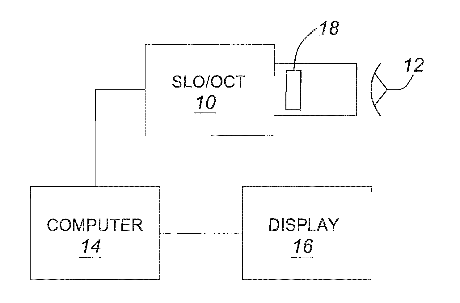
[0015]A commercially available combined SLO / OCT system is described, for example, in U.S. Pat. No. 6,769,769, the contents of which are herein incorporated by reference. Such an SLO / OCT system is capable of making OCT images of the eye or retina as well as SLO or confocal microscopic images.

[0016]In accordance with an embodiment of the invention, a visual acuity examination is performed while the patient's eye motion is tracked using high resolution SLO scans generated by the SLO-OCT system. As shown in FIG. 4, the SLO-OCT system 10 is brought up to the patient's eye 12, and a series of SLO images of the retina obtained by scanning. The confocal images are created by computer 14 from the SLO scans and displayed on display screen 16.

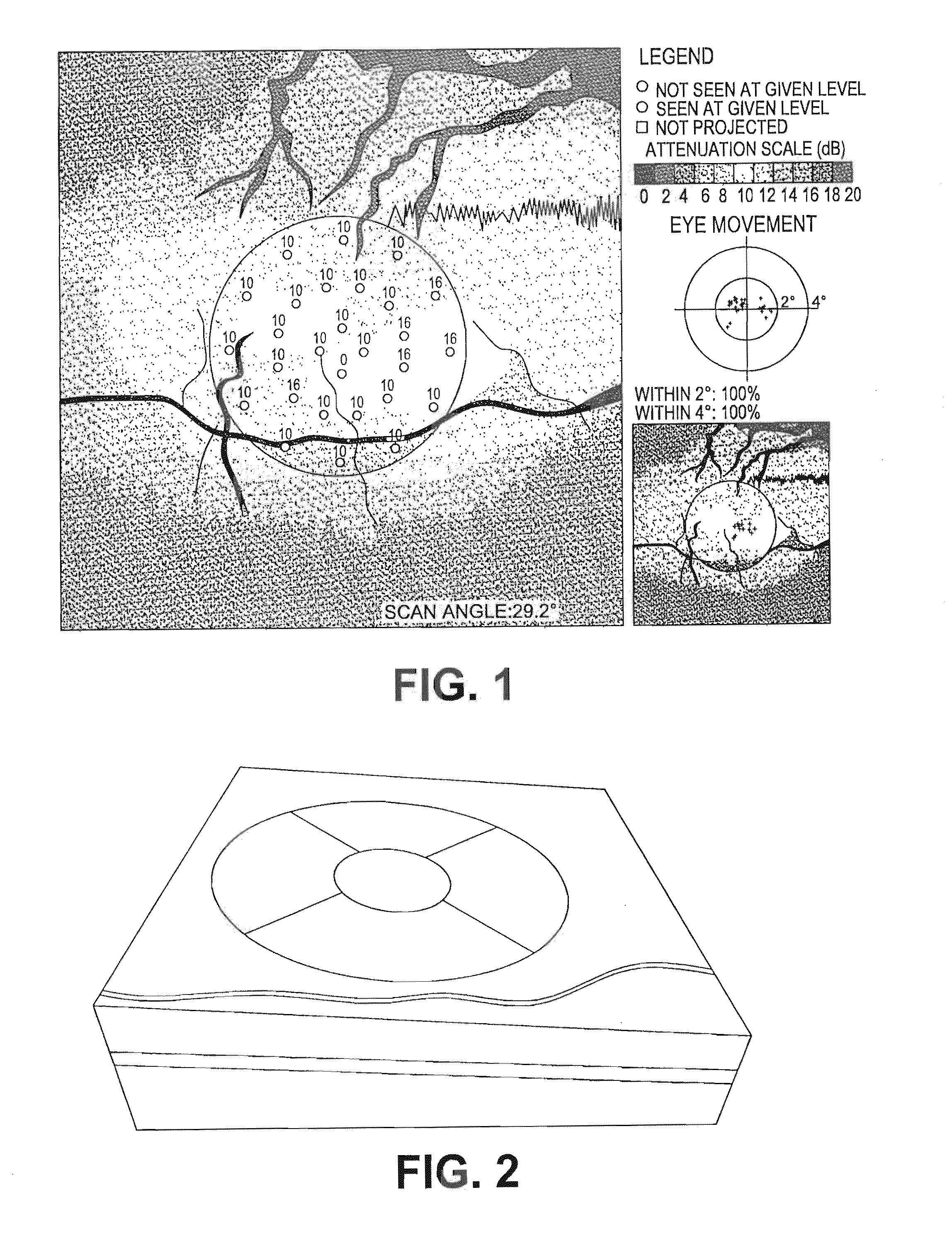
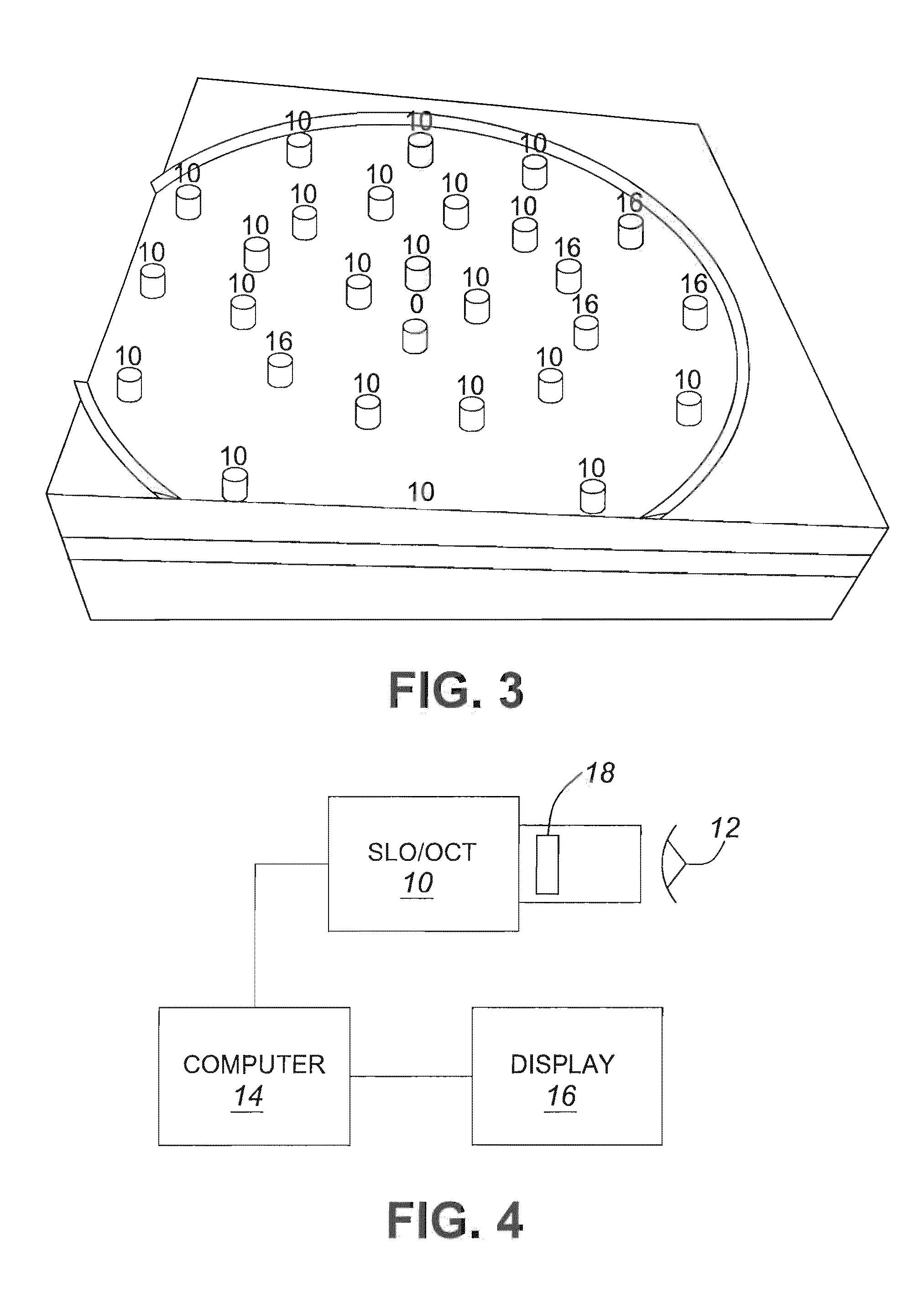
[0017]The SLO-OCT system 10 is able to track movement of the retina by comparing successive images. The tracking can be performed automatically in software in the computer 14 using any of a number of known algorithms suited for this purpose, such as a com...


PUM


Abstract

A visual acuity examination is performed on a patient by bringing a confocal imaging apparatus up to a patient's eye. Stimuli at various points in the patient's field of view are generated while the patient fixates on a point. The patient's responses to the stimuli are recorded with the movement of the eye with is tracked with the aid of the confocal imaging apparatus. The position of said stimuli on the retina is corrected to take into account any movement of the eye between stimuli.

Description

CROSS REFERENCE TO RELATED APPLICATION[0001]This application claims the benefit of prior U.S. provisional application Ser. No. 60 / 985,465, filed Nov. 5, 2007, the contents of which are herein incorporated by reference.FIELD OF THE INVENTION[0002]This invention relates to field of opthalmological examination, and in particular to a method for performing micro-perimetry and visual acuity examinations of a patient.BACKGROUND OF THE INVENTION[0003]Visual field tests designed to map a person's visual field and document the level of peripheral vision are a mainstay in opthalmology. Such tests are used to assess disease and treatment progressions. Typically, the test consists of having the patient respond every time a flash of light is perceived while the patient looks straight ahead, fixating onto a point. Visual acuity is normally tested using charts projected onto a wall where the patient is asked to read letters. Perimetry examination are used to test point locations on the retina and ...

Claims


Application Information

Patent Timeline
Patent Type & Authority Patents(United States)
IPC IPC(8): A61B3/00A61B3/02
CPCG01B9/0203G01B9/02077G01B9/02091A61B3/1025A61B5/0068
Inventor WEITZ, RISHARDMCLEAN, DUNCANROGERS, JOHNPEDRO, JUSTIN
Owner OPTOS PLC
Why Eureka
Try Eureka