Roller bearing cage and tapered roller bearing

a roller bearing and tapered roller bearing technology, applied in the field of roller bearing cages, can solve the problems of difficult manufacturing of cages, damage or cracking of parts of pillars, etc., and achieve the effect of preventing damage or cracking, easy manufacturing, and convenient manufacturing

Inactive Publication Date: 2010-05-25
JTEKT CORP
View PDF15 Cites 22 Cited by
  • Summary
  • Abstract
  • Description
  • Claims
  • Application Information

AI Technical Summary

Benefits of technology

[0007]The invention has been made to solve the above-described problems inherent in the related art. It is an object of the invention to provide a roller bearing cage that are capable of preventing a pillar portion from being damaged or cracked at the time of a tapered roller being forcibly fitted to a pocket, satisfying required physical properties, such as strength, a heat resistance, and an oil resistance, and being easily manufactured, and a tapered roller bearing using the roller bearing cage.
[0015]In the roller bearing cage according to the aspect of the invention, when the tapered roller is forcibly fitted to the pocket, the stress that is applied to the pillar portion is alleviated by the stress alleviating portion. Therefore, the strong stress is not applied to the pillar portions in the assembling process, and the cage can be prevented from being cracked. Further, since the material forming the cage does not need to have flexibility so as to alleviate the stress, a resin having high rigidity can be used. In addition, it is possible to use a resin capable of satisfying required physical properties, such as a heat resistance and an oil resistance. Furthermore, since the stress alleviating portion is formed so that a portion of the pillar portion from a crossing portion between the pillar portion and the small-diameter annular portion to a side of the large-diameter annular portion is linearly cut, the cage can be easily manufactured without requiring a complicated mold structure.
[0019]In this case, since the tapered rollers are smoothly mounted by the cage, the tapered rollers can be reliably assembled.
[0023]According to the tapered roller bearing according to another aspect of the invention, the tapered roller bearing uses a cage that can be prevented from being damaged or cracked, can satisfy required physical properties, such as intensity, a heat resistance, and an oil resistance, and can be easily manufactured. Therefore, the tapered roller bearing can be easily manufactured, and has high durability.
[0024]According to the aspects of the invention, the stress alleviating portions are provided to alleviate the stress applied to the pillar portions, and each of the stress alleviating portions is composed of a cutout portion that linearly extends from the crossing portion between the pillar portion and the small-diameter annular portion to the side of the large-diameter annular portion. Therefore, the roller bearing cage can be easily manufactured which can prevent the pillar portions from being damaged or cracked when the tapered rollers are forcibly fitted to the pockets and satisfy required physical properties, such as the intensity, the heat resistance, and the oil resistance.

Problems solved by technology

When the resin having high rigidity is used, the strong stress may be applied to the pillar portions due to elastic deformation by the tapered roller, and a portion of the pillar portions may be damaged or cracked.
The above-described problems may occur when a rib is provided on the small diameter side of the inner ring member.
In this case, since a mold structure for forming the cage becomes complicated, it becomes difficult to manufacture the cage.

Method used


Image

  • Roller bearing cage and tapered roller bearing
  • Roller bearing cage and tapered roller bearing
  • Roller bearing cage and tapered roller bearing

Examples


first embodiment

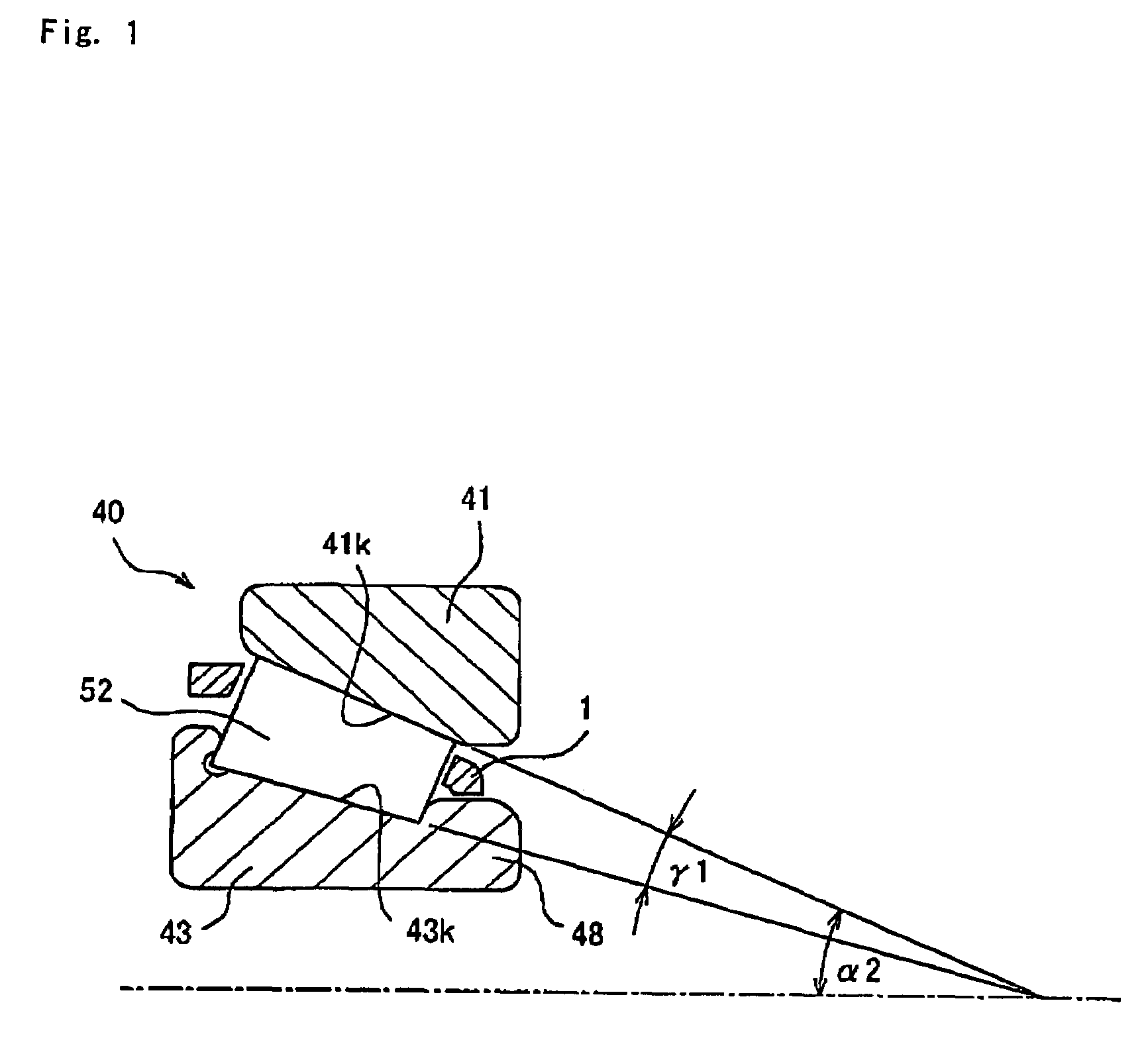
[0032]Hereinafter, the preferred embodiments of the invention will be described with reference to the accompanying drawings. FIG. 1 is a diagram illustrating a tapered roller bearing 40 according to the invention in which a roller bearing cage (hereinafter, referred to as cage) 1 is used. A tapered roller bearing 40 according to this embodiment includes a single outer ring member 41 that is provided with an outer ring raceway 41k whose size is increased from one side to the other side, an inner ring member 43 that is provided with an inner ring raceway 43k whose size is increased from one side to the other side, a plurality of tapered rollers 52 that are interposed rotatably between the inner ring raceway 43k and the outer ring raceway 41k facing each other, and a cage 1 that retains the plurality of tapered rollers 52 at predetermined intervals in a circumferential direction.

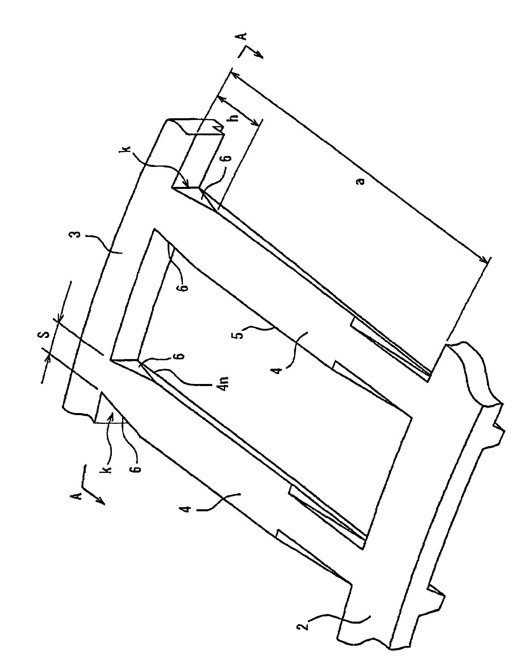
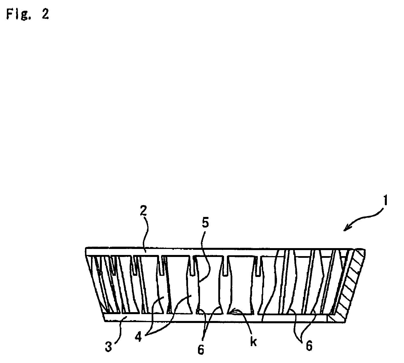
[0033]As shown in FIG. 2, the cage 1 includes a large-diameter annular portion 2 and a small-diameter annula...

second embodiment

[0038]FIG. 5 is a diagram illustrating a tapered roller bearing according to the invention where the cage 1 is used. The tapered roller bearing according to this embodiment is constructed as a rolling bearing device 50. The rolling bearing device 50 includes a single outer ring member 51 that is provided with a pair of outer ring raceways 51k whose sizes are increased from the central portion of the outer ring member 51 to opposite end sides thereof in the axial direction, a hub ring 55 that has a flange 54 at one end side of the hub ring 55 in the axial direction and is provided with an inner ring raceway 55k, an inner ring member 53 that is fitted around a small-diameter portion 55s of the hub ring 55 and is provided with an inner ring raceway 53k, a plurality of tapered rollers 52 that are rotatably disposed on inner and outer ring raceway surfaces facing each other, a cage 1 that retains the tapered rollers 52 at predetermined gaps in a circumferential direction, and a sealing m...


PUM


Abstract

A roller bearing cage is made of a resin and has a tapered tubular shape as a whole. In the roller bearing cage, tapered rollers are forcibly fitted to pockets while elastically deforming pillar portions at a small-diameter annular portion side. A stress alleviating portion is provided on at least an outer circumferential side of an end of the pillar portion at the small-diameter annular portion side so that a portion of the pillar portion from a crossing portion between the pillar portion and the small-diameter annular portion to a side of the large-diameter annular portion is linearly cut, thereby alleviating the stress occurring in the pillar portion when the tapered roller is forcibly fitted to the pocket.

Description

BACKGROUND OF THE INVENTION[0001]The present invention relates to a roller bearing cage that is made of a resin and is used for a roller bearing and a tapered roller bearing that uses the roller bearing cage.[0002]A cage, which is incorporated in a tapered roller bearing used in a transmission device or a differential device of a vehicle, an axel of a railroad vehicle or an industrial machine, or a tapered roller bearing of a hub unit bearing disclosed in Patent Document 1, is made of a resin material that has smaller weight than a metal material and excellent productivity and economical efficiency. Generally, the cage that is made of the resin material includes a large-diameter annular portion and a small-diameter annular portion that are concentrically disposed on opposite sides of the cage in an axial direction, and a plurality of pillar portions that extend between the large-diameter annular portion and the small-diameter annular portion at a plurality of locations in a circumfe...

Claims


Application Information

Patent Timeline
Patent Type & Authority Patents(United States)
IPC IPC(8): F16C33/46
CPCF16C19/364F16C33/4635F16C33/4676F16C43/08F16C19/386F16C2240/40F16C2326/02F16C33/56
Inventor TABATA, MASAHIROKUROKAWA, TAKANORI
Owner JTEKT CORP
Why Eureka
Try Eureka