Surgical guiding instrument

a guiding instrument and surgical technology, applied in the field of surgical guiding instruments, can solve problems such as affecting the area of the vertebral column, machining tools, chisels or milling tools, etc., and achieve the effect of preventing unintentional injury to the vertebral column by surgical procedures

Active Publication Date: 2010-07-06
AESCULAP AG
View PDF10 Cites 42 Cited by
  • Summary
  • Abstract
  • Description
  • Claims
  • Application Information

AI Technical Summary

Benefits of technology

[0007]The further development according to the invention has the advantage that the preparation of the vertebral bodies prior to insertion of an intervertebral implant with fin-like projections is considerably simplified. In particular, the guiding instrument can be inserted, more specifically, through a minimally invasive access, and, after insertion, the stop device can be actuated by the actuating member from outside the body of the human being or animal, in order to adjust the stop. Accordingly, a maximum insertion depth of a surgical machining tool can also be optionally altered by altering the relative position between stop and implant body of the guiding instrument. This can be done with, for example, the assistance of X-ray monitoring, so as to ensure that when machining the vertebral bodies adjoining the intervertebral space only as much material is removed from the respective vertebral body as is actually required for insertion of the intervertebral implant. In addition, when preparing the vertebral bodies, the machining tool is thereby prevented from entering the spinal canal and causing injury.
[0047]In order to ensure, when preparing the at least one vertebral body, that the intervertebral implant to be inserted can be optimally fitted into the intervertebral space, it is advantageous for a guiding instrument with an implant body to be selected, and for a height of the implant body and an angle between the implant bearing surfaces of the implant body to correspond to a height and an angle of an implant for implantation. Accordingly, when an operator has decided which implant is to be inserted into the intervertebral space, he can select the corresponding guiding instrument. In particular, this has the advantage that he can form the recess in the respective vertebral body with the machining tool without any further deliberation and without fear of any undesirable injury to the vertebral column.

Problems solved by technology

Degenerative processes in the intervertebral disks articulatedly joining adjacent vertebral bodies of the vertebral column to one another are often the cause of disorders in the area of the vertebral column.
When doing so, a problem arises with the machining tool, for example, a chisel or a milling tool, being advanced ventrally too far into the intervertebral space in the direction towards the spinal canal of the spinal column.
Minimally invasive surgery would then be virtually impossible.

Method used


Image

  • Surgical guiding instrument
  • Surgical guiding instrument
  • Surgical guiding instrument

Examples


Embodiment Construction

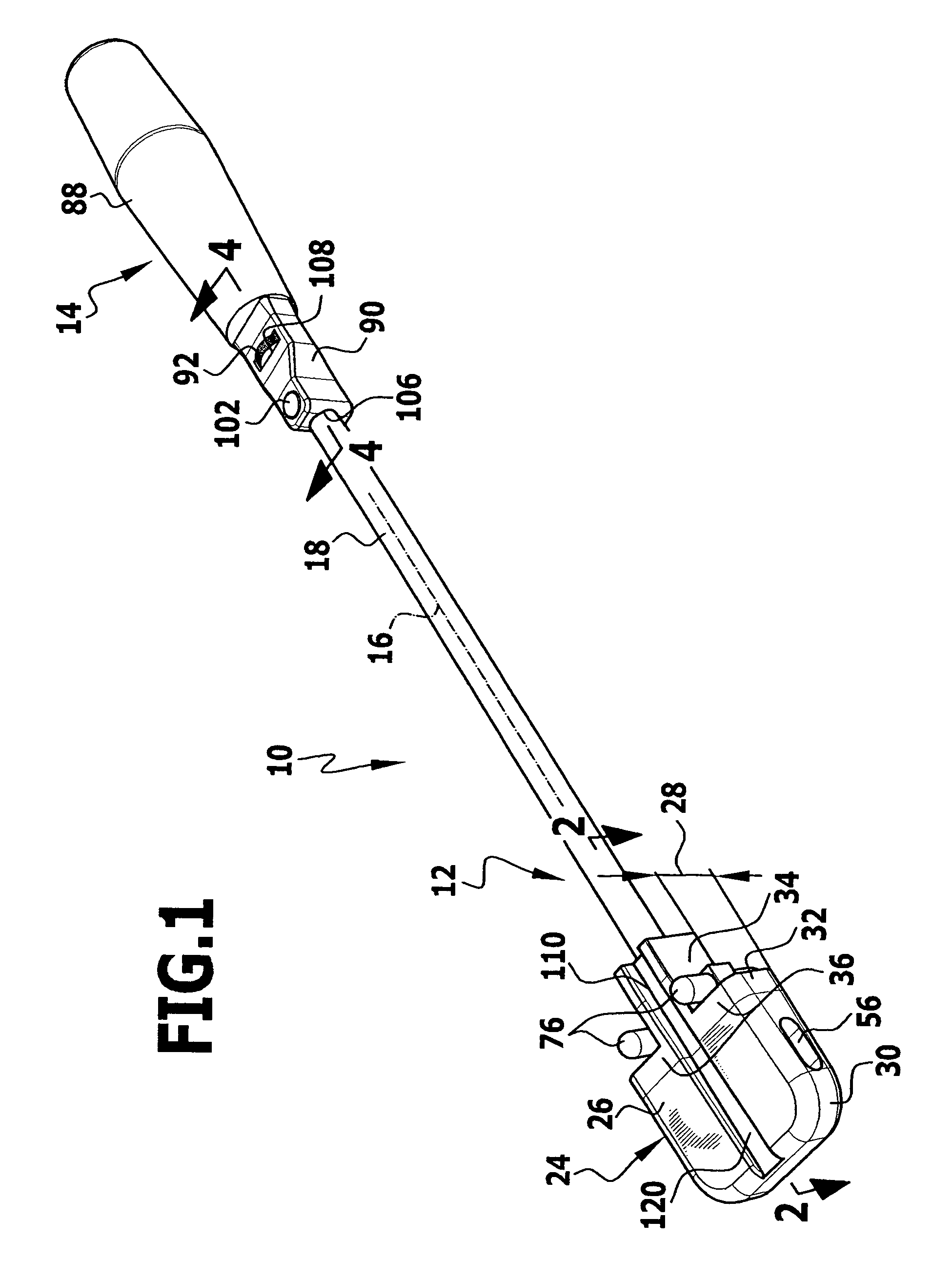
[0053]FIG. 1 shows a surgical guiding instrument, generally designated by reference numeral 10, which essentially comprises two parts, namely a shaft part 12 and a handle part 14, which are releasably connectable to one another.

[0054]The shaft part 12 comprises an elongated hollow shaft 18 defining a longitudinal axis 16 and having in the proximity of a proximal end two diametrically opposed flat portions.

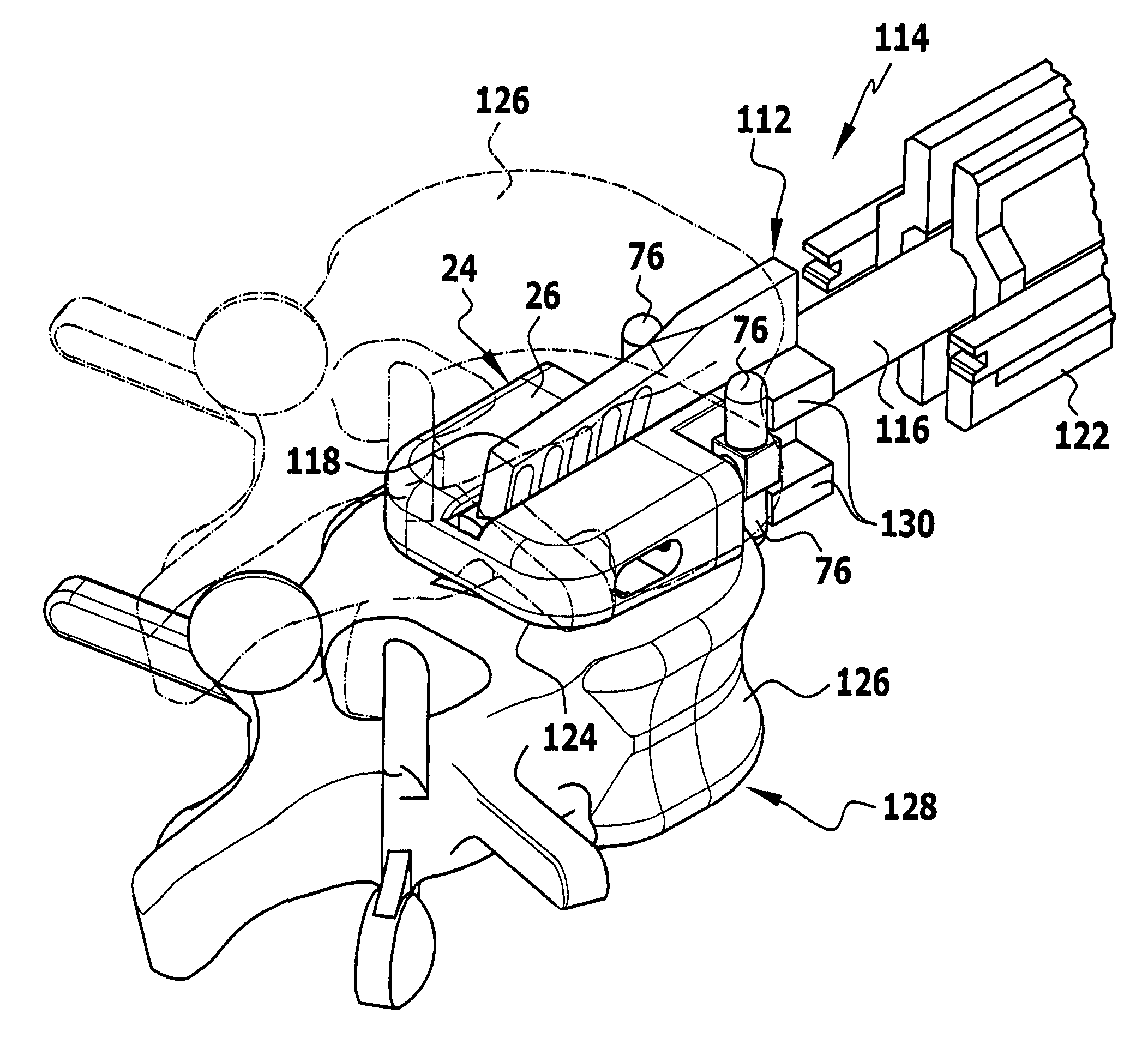
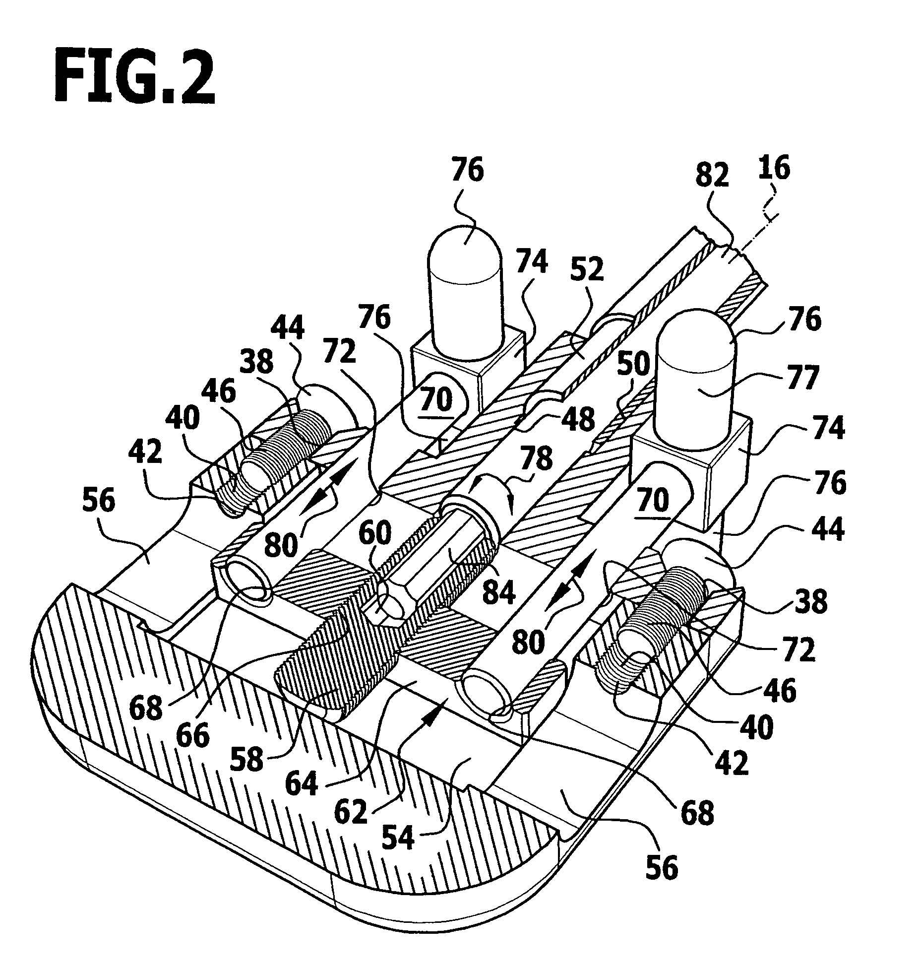
[0055]Arranged at a distal end of the shaft 18 is an implant body 24 of essentially cuboidal shape, which comprises two bearing surfaces which point in opposite directions and are inclined at an angle of inclination 28 relative to one another. Depending on the purpose for which the guiding instrument 10 is to be used, the angle of inclination 28 may assume values ranging from 0° to 30°. The implant body 24 is of two-part construction and comprises a front part 30 and a rear part 32, the rear part 32 being of essentially T-shaped design. The rear part 32 comprises a middle body 34 w...


PUM


Abstract

A surgical guiding instrument for use with a chisel and an implant body for insertion into an intervertebral space, included is a shaft with a stop device for delimiting a depth of insertion of the implant body into the intervertebral space. The shaft has a distal end and a proximal end, the implant body being arranged at the distal end of the shaft and defining two bearing surfaces positionable against the adjacent vertebral bodies, the stop device having at least one stop movably mounted at the distal end of the shaft or on the implant body, the stop having a stop surface pointing in distal direction transversely or substantially transversely to at least one of the bearing surfaces, so that an insertion depth for a surgical machining tool can be set in a simple way.

Description

[0001]This application claims priority to German Application No. 10 2005 056 824.6, filed Nov. 24, 2005, which is incorporated herein by reference in its entirety.BACKGROUND OF THE INVENTION[0002]The present invention relates to a surgical guiding instrument for a surgical machining tool, in particular, a chisel, with an implant body for insertion into an intervertebral space between adjacent vertebral bodies of the vertebral column of a human being or an animal, with a shaft and with a stop device for delimiting a depth of insertion of the implant body into the intervertebral space, the shaft having a distal end and a proximal end, the implant body being arranged at the distal end of the shaft and defining two bearing surfaces positionable against the adjacent vertebral bodies, the stop device having at least one stop movably mounted at the distal end of the shaft or on the implant body, the stop having a stop surface pointing in distal direction transversely or substantially trans...

Claims


Application Information

Patent Timeline
Patent Type & Authority Patents(United States)
IPC IPC(8): A61F2/00A61B17/60A61B17/00A61B17/58
CPCA61B17/1671A61B17/1757A61F2/4684A61B17/1604A61B2017/0256A61B2019/304A61F2002/30616Y10S606/914A61B2090/034
Inventor FISCHER, KAYSCHULTZ, ROBERT
Owner AESCULAP AG
Why Eureka
Try Eureka