Blower system having a cooling passage

a technology of blower and cooling passage, which is applied in the direction of positive displacement liquid engine, piston pump, liquid fuel engine, etc., can solve the problems of extremely poor maintenance efficiency and air-conditioning case, and achieve the effect of convenient maintenan

Active Publication Date: 2010-08-24
DENSO CORP
View PDF8 Cites 14 Cited by
  • Summary
  • Abstract
  • Description
  • Claims
  • Application Information

AI Technical Summary

Benefits of technology

[0010]An object of the present invention is to provide a blower system which is easy to maintain and obtains motor cooling air from the inside of the spiral casing.
[0012]In the blower system, the blower case and the motor holding housing are comprised as separate members, so when replacing the motor, there is no need to disassemble the blower case 1. The motor can be easily replaced by detaching the motor holding housing to which the motor is mounted from the blower case. Further, due to the above cooling air passage structure, the ease of motor replacement can be maintained and motor cooling air can be obtained from the inside of the spiral casing.
[0013]Preferably, the inlet opening (2a) is provided with inclined walls (2f) formed inclined with respect to the diametrical direction so as to enlarge the cross-sectional area of the passage toward the outside in the diametrical direction of the spiral casing (1a) and guiding the cooling air (x). Due to this, part of the air circulated through the inside of the spiral casing easily flows into the cooling air passage and as a result the flow rate of the cooling air can be made larger.
[0014]More preferably, the cooling air passage (4) is provided with a partition wall (2g) formed continuing with the extension (2h) and covering the blower fan side of the cooling air passage. Due to this, it is possible to prevent the sound of the stream of air striking the cooling air and to increase the cooling air low rate.
[0019]Still more preferably, the inlet opening (2a) is arranged between a spiral start (1x) and a spiral end (1y) of a spiral shape forming a functional part of the spiral casing (1a) and corresponding to a position shifted from the spiral start (1x) to the spiral end (1y) in a direction (−θ) opposite to the spiral direction (+θ). Due to this, it becomes possible to further increase the cooling air flow rate.

Problems solved by technology

However, this blower system is an integral structure of the lower piece P2 of the blower vase 1 and the motor holding housing 2 joined together, so when the motor M has to be replaced, it becomes necessary to separate the upper piece P1 and lower piece P2 of the blower case 1 to remove the motor M. Usually, the blower case 1 is connected to the air-conditioning case having the cooler and heater, so when disassembling the blower case 1, it becomes necessary to disassemble the air-conditioning case and the maintenance efficiency becomes extremely poor.

Method used


Image

  • Blower system having a cooling passage
  • Blower system having a cooling passage
  • Blower system having a cooling passage

Examples


first embodiment

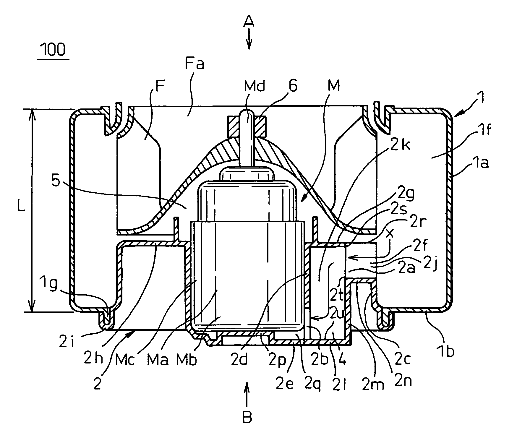
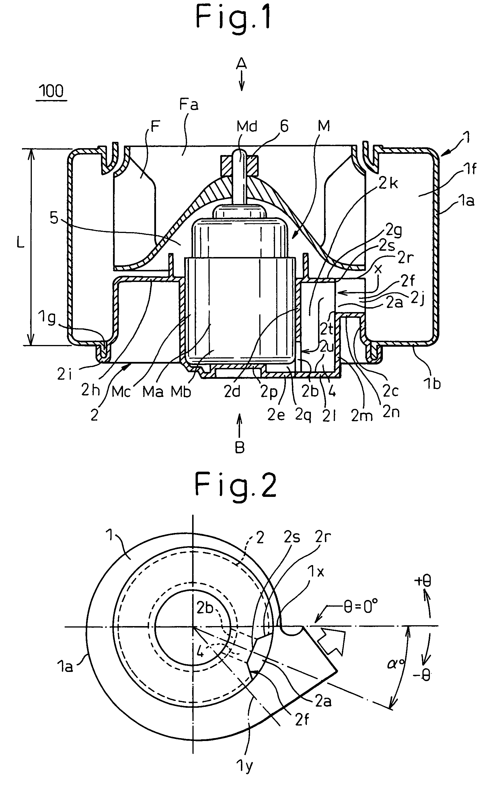
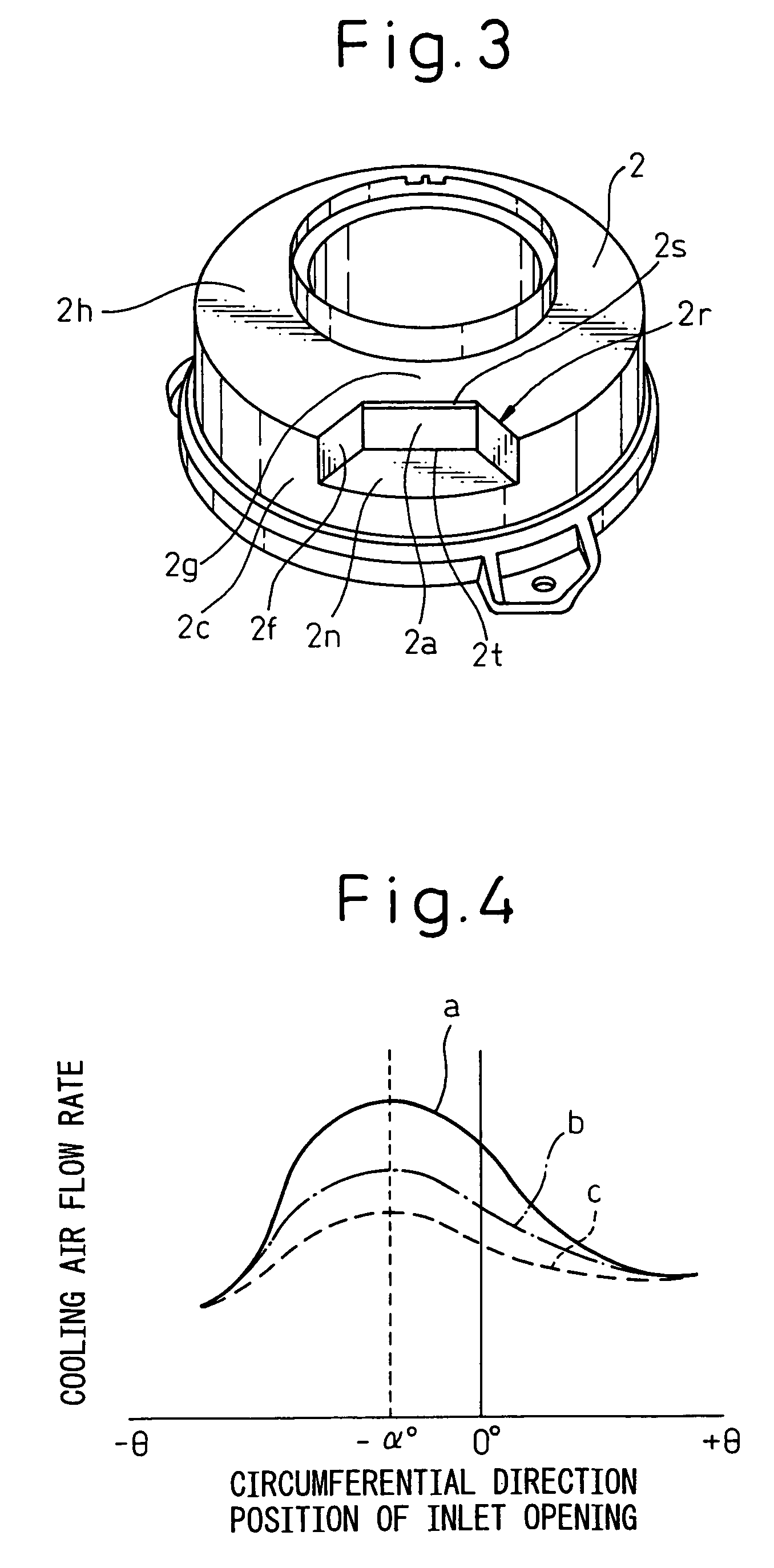
[0034]FIG. 1 is a cross-sectional view of a blower system according to a first embodiment of the present invention, FIG. 2 is a schematic top view of a blower system as seen from the direction A in FIG. 1, and FIG. 3 is a perspective view of a motor holding housing of a blower system according to the first embodiment of the present invention.

[0035]In FIG. 1, 100 indicates a blower system according to the present invent, F a centrifugal type blower fan, M a motor, 1 a blower case, 2 a rotor holding housing, 4 a cooling air passage, and 6 a fan fastening nut. 2a, 2b, 2c, 2d, 2e, 2f, and 2g show parts of the motor holding housing 2, where 2a shows an inlet opening, 2b an outlet opening, 2c a circumferential wall forming the spiral casing, 2d a side wall fastening and holding the motor side surface Mc, 2e a floor abutting against and holding the motor bottom Mb, 2f an inclined wall guiding the cooling air x, and 2g a partition wall. The blower case 1 and the motor holding housing 2 are ...


PUM


Abstract

A blower system, wherein a blower case and a motor holding housing are comprised as separate members, a spiral casing is provided with an enlarged part enlarged in an axial direction to an opposite side from the suction port from a centrifugal type blower fan. The motor holding housing is provided with a holder storing and holding the motor, an extension extending from the holder in a diametrical direction of the fan, a circumferential wall connected with the extension and forming an inner circumferential wall of the enlarged part in the spiral casing. A cooling air passage is provided between the holder and the circumferential wall to guide part of the air circulating inside the spiral casing to the motor. The cooling air passage has an inlet into which air flows from the spiral casing and an outlet at the circumferential wall, out of which air flows to the motor.

Description

BACKGROUND OF THE INVENTION[0001]1. Field of the Invention[0002]The present invention relates to a blower system for a vehicular air-conditioning system etc.[0003]2. Description of the Related Art[0004]In general, a vehicular air-conditioning system is provided at the front of the front seats in the passenger compartment. It has an intake having a blower system for obtaining air from inside and outside of the compartment, a cooler for cooling the obtained air, and a heater for heating the cooling air.[0005]The blower system provided at the intake is also disclosed in Japanese Patent Publication (A) No. 2002-347423. For example, as shown in FIG. 10, it has a blower case 1 in which a centrifugal type blower fan F is housed and a motor M driving the blower fan F. When this motor 14 drives the blower Fan F, the air inside the compartment or the air outside the compartment is selectively taken into the blower case 1 from an intake port 3 (also called a “bellmouth”) and flows from a disch...

Claims


Application Information

Patent Timeline
Patent Type & Authority Patents(United States)
IPC IPC(8): F04B39/06
CPCF04D25/082F04D29/5806
Inventor ARAKI, YOSHINORI
Owner DENSO CORP
Why Eureka
Try Eureka