Method of calculating power flow solution of a power grid that includes generalized power flow controllers

a technology of power flow and power grid, applied in the direction of process and machine control, electric generator control, electric devices, etc., can solve problems such as oscillation or even divergence of solutions, and achieve the effect of rapid convergen

Inactive Publication Date: 2010-10-12
CHANG GUNG UNIVERSITY
View PDF8 Cites 31 Cited by
  • Summary
  • Abstract
  • Description
  • Claims
  • Application Information

AI Technical Summary

Benefits of technology

[0013]It is, therefore, an object of the present invention to provide a method to incorporate the steady-state model of a generalized power flow controller into a Newton-Raphson power flow algorithm with a robustness and rapid convergence characteristic, wherein the convergence speed is not sensitive to the selection of initial values of control variables of the generalized power flow controller.
[0015]To carry out previously mentioned objects, an innovative steady-state model of the generalized power flow controller is disclosed. The steady-state model has a flexible structure, wherein the sending-end of each series VSC isn't confined to connect to the same bus as the shunt converter is connected. The feature of the steady-state model is expressing the variables of the steady-state model in a rectangular coordinate. Transforming the phasor from a conventional polar coordinate into d-q components reduces the appended state variables in the Newton-Raphson iteration. As a result, the increased iterations introduced by the generalized power flow controller is fewer than the prior art. The power flow calculation can preserve a rapid convergence characteristic.

Problems solved by technology

Improper selection of the control variables may cause the solutions oscillating or even being divergent.

Method used


Image

  • Method of calculating power flow solution of a power grid that includes generalized power flow controllers
  • Method of calculating power flow solution of a power grid that includes generalized power flow controllers
  • Method of calculating power flow solution of a power grid that includes generalized power flow controllers

Examples


case 2

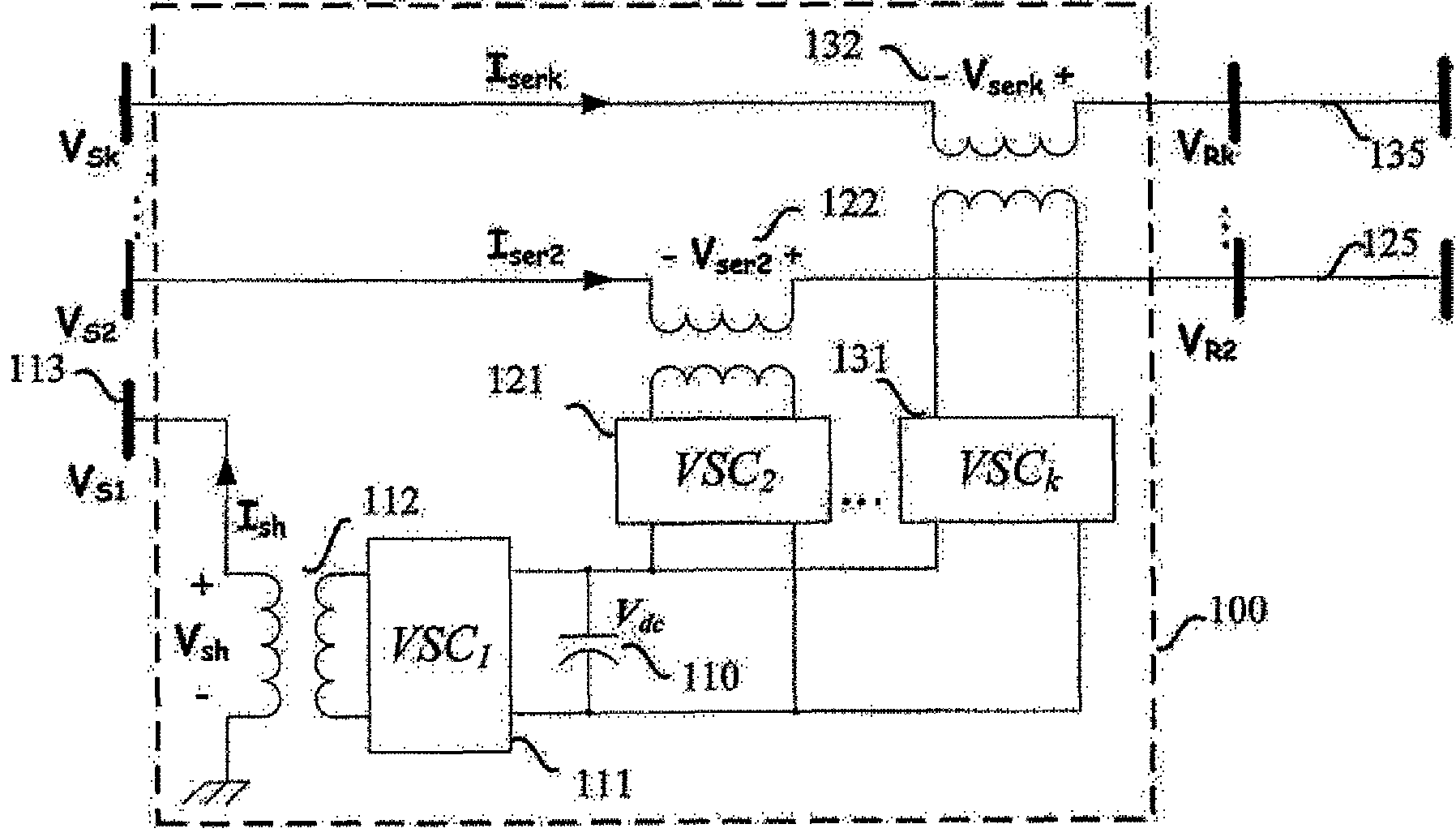
[0067] Similar to Case 1, except that it has been installed with one additional GUPFC 101. The GUPFC 101 has one shunt branch and three series branches. The shunt branch is in parallel with bus 37 to control its voltage magnitude. The series branches are in series with line 37-49 (the transmission line linking bus 37 and bus 49), line 37-89 and line 37-40, respectively, to control their active and reactive power flow.

case 3

[0068] Similar to Case 2, except that it has been installed with one additional generalized power flow controller, referred to as GPFC. GPFC has one shunt branch and two series branches. The shunt branches in parallel with bus 102 to control its voltage magnitude. The series branches are in series with line 102-104 and line 103-105, respectively, to control their active and reactive power flow.

case 4

[0069] Similar to Case 3, except that it has been installed with one additional UPFC 102. The UPFC 102 has one shunt branch and one series branch. The shunt branch is in parallel with bus 7 to control its voltage magnitude. The series branch is in series with line 7-131 to control its active and reactive power.


PUM


Abstract

A method to incorporate the steady-state model of the generalized power flow controller into a Newton-Raphson power flow algorithm adopts a flexible steady-state model of the generalized power flow controller, which can be applied to calculate the power flow solution of a power grid embedded with STATCOM, UPFC, GUPFC and the generalized power flow controller in a single framework. The method only incorporates the control variables of the shunt voltage sourced converter into the state vector of the Newton-Raphson power flow algorithm. The increment of the state variables due to incorporating the generalized power flow controller is less than the prior art. Further, the method can preserve the quadratic convergence characteristic of the Newton-Raphson power flow algorithm after embedding the generalized power flow controller into a power grid.

Description

BACKGROUND OF THE INVENTION[0001]1. Field of the Invention[0002]The present invention relates generally to the power flow analysis of a power grid embedded with a generalized power flow controller in the technical field and, more particularly, to a method to incorporate the steady-state model of a generalized power flow controller into a conventional Newton-Raphson power flow algorithm, which can be applied to calculate the power flow solution of a power grid embedded with the generalized power flow controller.[0003]2. Description of Related Art[0004]In the last decade, the power industry has extensively employed an innovative Flexible Alternative Current Transmission System (FACTS) technology to improve the utilization of existing transmission facilities. Connecting several Voltage Sourced Converters (VSCs) together forms various multiple functional FACTS controllers, such as: Static Synchronous Compensator (STATCOM) 103, Unified Power Flow Controller (UPFC) 102, and Generalized Un...

Claims


Application Information

Patent Timeline
Patent Type & Authority Patents(United States)
IPC IPC(8): G01R21/06
CPCH02J3/06H02J3/1814G01R19/2513Y02E40/16Y02E40/18Y02E40/10
Inventor CHU, CHIA-CHILEE, SHENG-HUEICHEN, CHUNG-HSIUNG
Owner CHANG GUNG UNIVERSITY
Why Eureka
Try Eureka