Vehicle frame structure

a frame structure and vehicle technology, applied in the direction of bicycles, transportation and packaging, cycle equipment, etc., can solve the problems of complicated structure of these members, and achieve the effect of ensuring the rigidity of the suspension supporting portion

Active Publication Date: 2010-10-26
HONDA MOTOR CO LTD
View PDF17 Cites 19 Cited by
  • Summary
  • Abstract
  • Description
  • Claims
  • Application Information

AI Technical Summary

Benefits of technology

[0009]According to the first aspect of the invention, the rigidity of the suspension supporting portion of the vehicle body frame is easily ensured by connecting the upper and lower frame members using the rear member. The accuracy in positioning of the respective suspension arm supporting portions is easily ensured by providing the supporting portions of the upper and lower suspension arms on a single member.
[0011]According to the second aspect of the invention, the desired rigidity of the rear member is obtained, and the rear member is formed into a shape which can easily hold the respective suspension arms in a simple structure.
[0013]According to the third aspect of the invention, rationalization in design of the vehicle body is achieved without requiring a dedicated member for supporting the terminal gear case by concentrating the supporting function of the terminal gear case and the respective suspension arms on the member which also serves as a reinforcing member of the vehicle body frame.
[0015]According to the fourth aspect of the invention, a structure which easily ensures the rigidity of a joined portion between the rear member and the respective frame members is achieved.
[0019]According to the sixth aspect of the invention, the vehicle body frame is easily assembled by assembling the left and right rear members and the mounting members to the respective frame members in a sub-assembled state in advance when integrally assembling the respective frame members, the left and right members and the mounting member.
[0023]According to the eighth aspect of the invention, the arm support portion and the stabilizer holding portion reinforce each other, thus easily ensuring the rigidity of the suspension supporting portion of the vehicle body frame.

Problems solved by technology

In the above-mentioned publication, members that require accuracy and rigidity are concentrated on a suspension supporting portion (sub-frame) of the vehicle body frame and, in addition, these members are required to have special shapes or parts respectively and hence, the structures of these members tend to become complicated.

Method used


Image

  • Vehicle frame structure
  • Vehicle frame structure
  • Vehicle frame structure

Examples


first embodiment

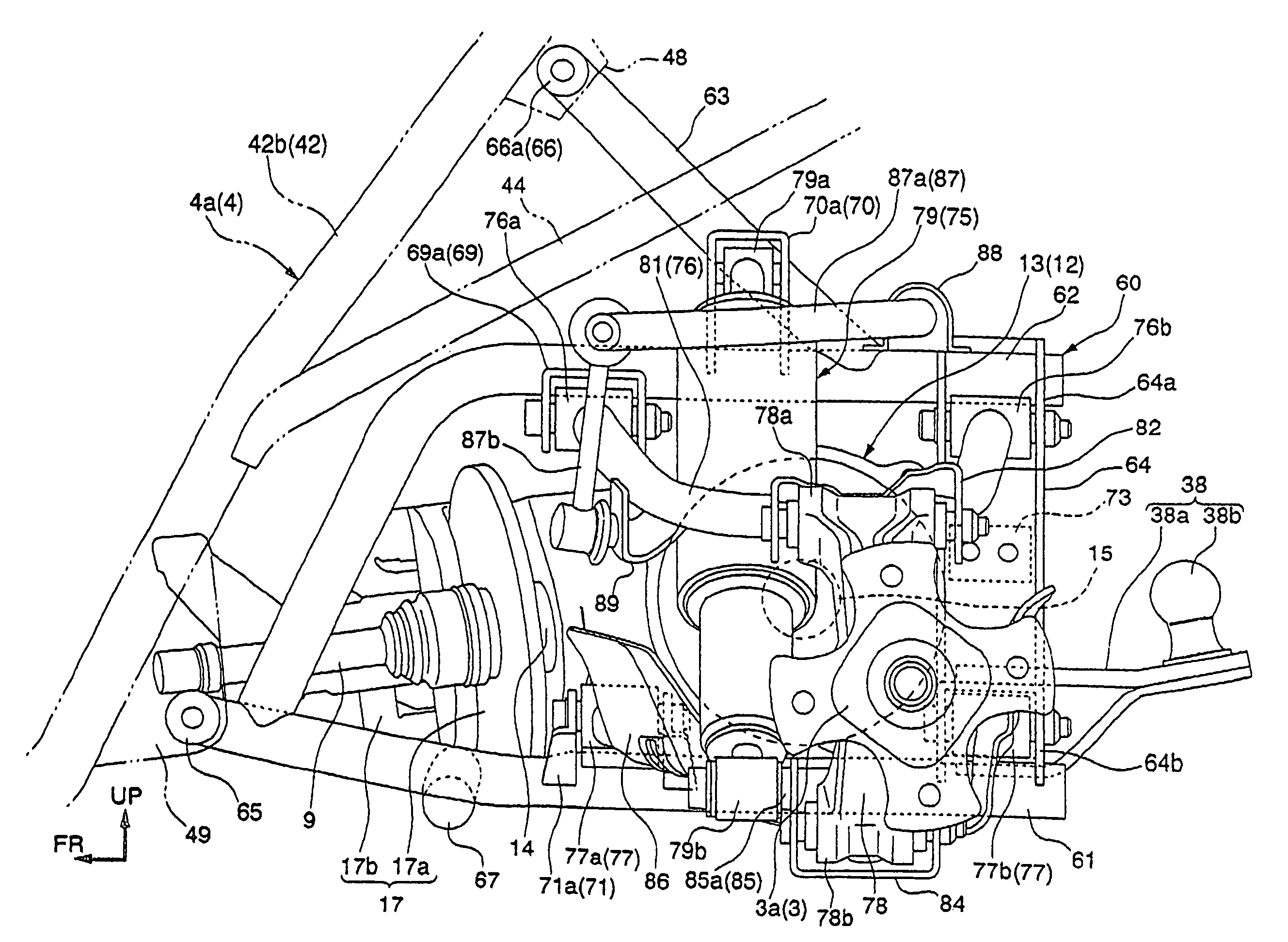
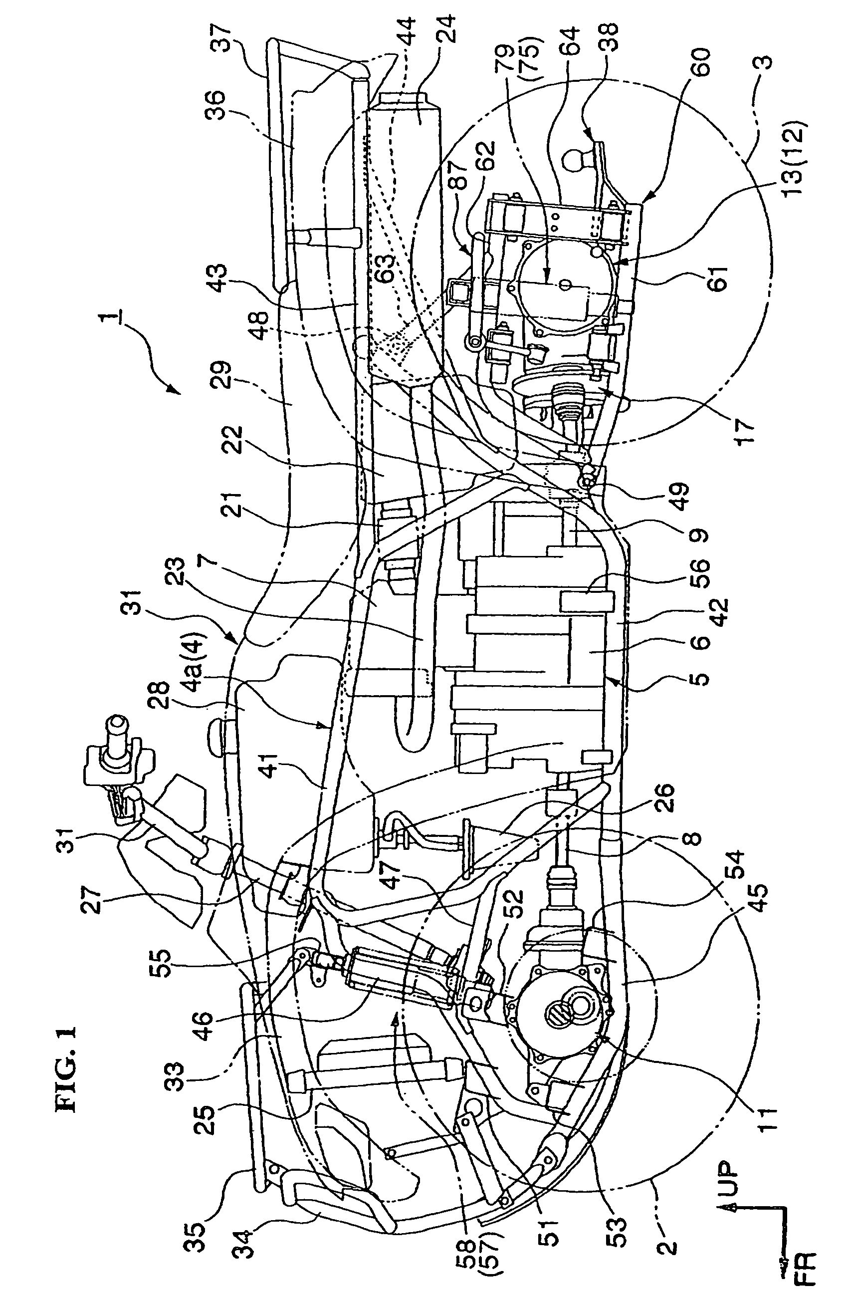
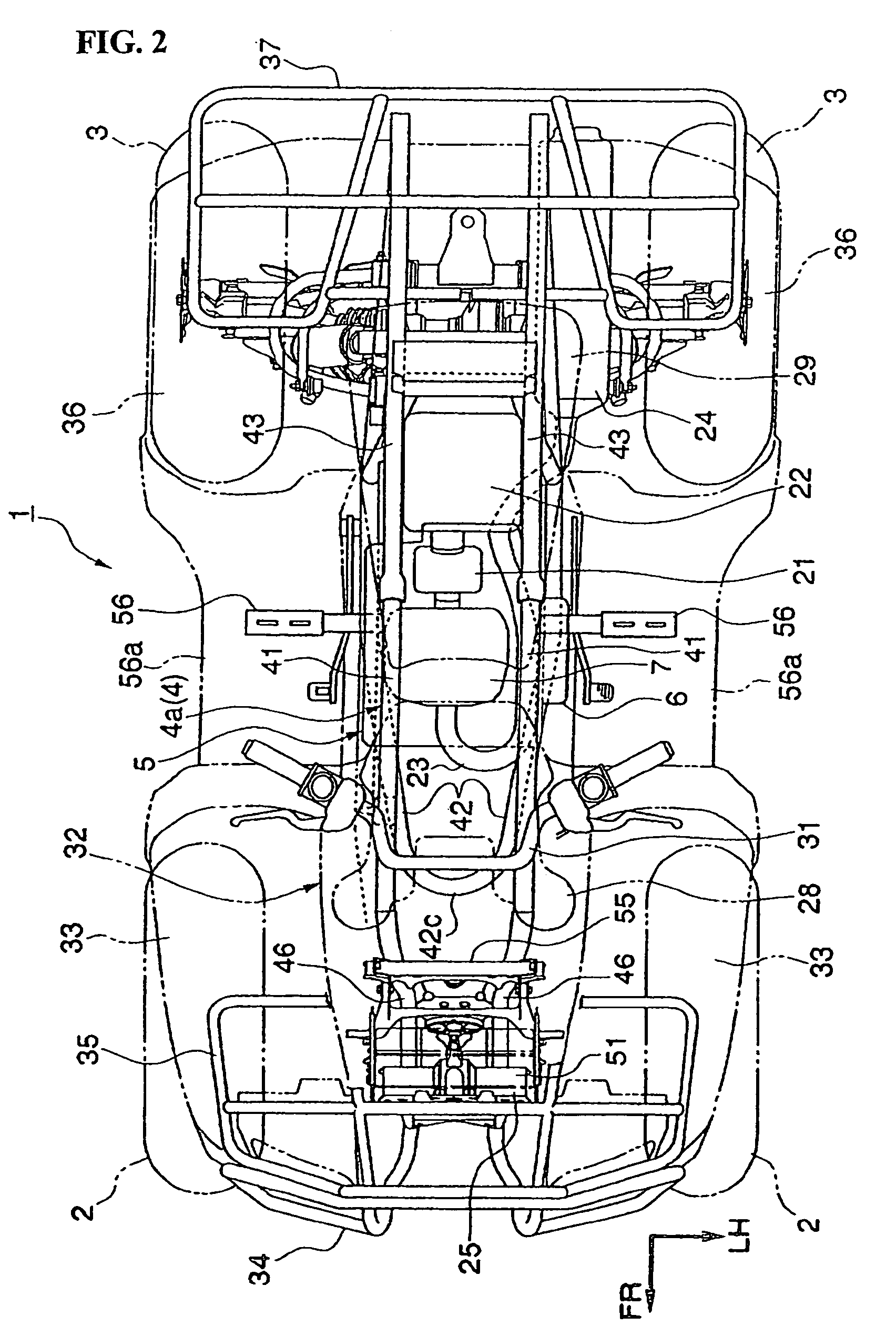
[0039]the invention is now described with respect to a saddle-type four-wheel vehicle 1 designed for operation on rough-terrain, commonly referred to as an ATV and shown in FIG. 1. The vehicle 1 includes left and right front wheels 2 and rear wheels 3. The wheels 2, 3 are low-pressure balloon tires of relatively large diameter provided at the front and rear of the vehicle body. The vehicle body is configured to be compact and light in weight, and has a large minimum ground clearance for enhancing traveling performance mainly on the rough terrain. A vehicle body frame 4 of this saddle-type four-wheel vehicle 1 includes a separate sub-frame 60 integrally connected to the rear portion of a frame body 4a.

[0040]Both of the front wheels 2 are suspended by way of front suspensions 57. The front suspensions 57 are of an independent suspending type (double wishbone type). Both of the rear wheels 3 are suspended at the rear portion (sub-frame 60) of the vehicle body frame 4 by way of rear su...

second embodiment

[0101]Next, the invention is hereinafter explained in conjunction with FIG. 10 to 12.

[0102]The second embodiment differs from the above-mentioned first embodiment in that a sub-frame 160 is adopted in place of the sub-frame 60. In the following description of the second embodiment, parts identical with the parts shown in the first embodiment are given the same symbols and corresponding explanation is omitted.

[0103]The sub-frame 160 is integrally connected to a rear portion of the frame body 4a in the same manner as the above-mentioned sub-frame 60, and suspends the left and right rear wheels 3 by way of the rear suspensions 75 of the independent suspension type (double wishbone type).

[0104]The sub-frame 160 is integrally formed by joining plural kinds of steel members by welding or the like. To be more specific, the sub-frame 160 mainly includes left and right sub-frame lower pipes 161 which extend rearwardly in a slightly downward and rearward extending state from the lower frame c...


PUM


Abstract

A frame structure is provided in which a sub-frame is fixed to a rear portion of a vehicle body frame, and serves as a suspension-supporting portion of the vehicle body frame. In the sub-frame, a rear member extends between a sub-frame upper pipe and a sub-frame lower pipe. The rear member includes a rear upper arm supporting portion and a rear lower arm supporting portion, for supporting proximal ends of an upper arm and a lower arm of a rear suspension. The frame structure hereof improves accuracy and rigidity of the suspension-supporting portion of the vehicle body frame, and provides a simplified structure as compared to conventional frame structures.

Description

CROSS-REFERENCE TO RELATED APPLICATIONS[0001]The present invention claims priority under 35 USC 119 based on Japanese patent application Nos. 2006-022881, filed on Jan. 31, 2006 and 2006-308831, filed on Nov. 15, 2006. The subject matter of these priority documents is incorporated by reference herein.BACKGROUND OF THE INVENTION[0002]1. Field of the Invention[0003]The present invention relates to a frame structure for a vehicle provided with wheels on the left and right sides of a vehicle body, such as an All Terrain Vehicle (ATV).[0004]2. Description of the Background Art[0005]In the vehicle frame art, a frame structure is known in which the rear portion of a vehicle body frame is formed as a sub-frame, and an independent rear suspension is supported by the sub-frame. Such a frame structure is disclosed, for example, in JP-A-2001-328410. As seen in FIG. 5 of that document, a sub-frame is disclosed which includes upper and lower separate frame members, and the lower frame member is f...

Claims


Application Information

Patent Timeline
Patent Type & Authority Patents(United States)
IPC IPC(8): B62D21/11B62D21/08B62K5/00B62K5/01B62K25/26
CPCB60D1/488B60G3/20B60G7/008B62K5/01B60G2200/144B60G2200/422B60G2202/135B60G2204/1224B60G2204/129B60G2204/148B60G2206/11B60G2206/50B60G2300/124
Inventor TSURUTA, YUICHIROYAMAGUCHI, MASAHIROOSADA, JIN
Owner HONDA MOTOR CO LTD
Why Eureka
Try Eureka