Method for forming a color image
a color image and image technology, applied in the field of color image formation, can solve the problems of destroying color balance, affecting color correction, and changing the optical density of the output image,
- Summary
- Abstract
- Description
- Claims
- Application Information
AI Technical Summary
Benefits of technology
Problems solved by technology
Method used
Image

Examples
first embodiment
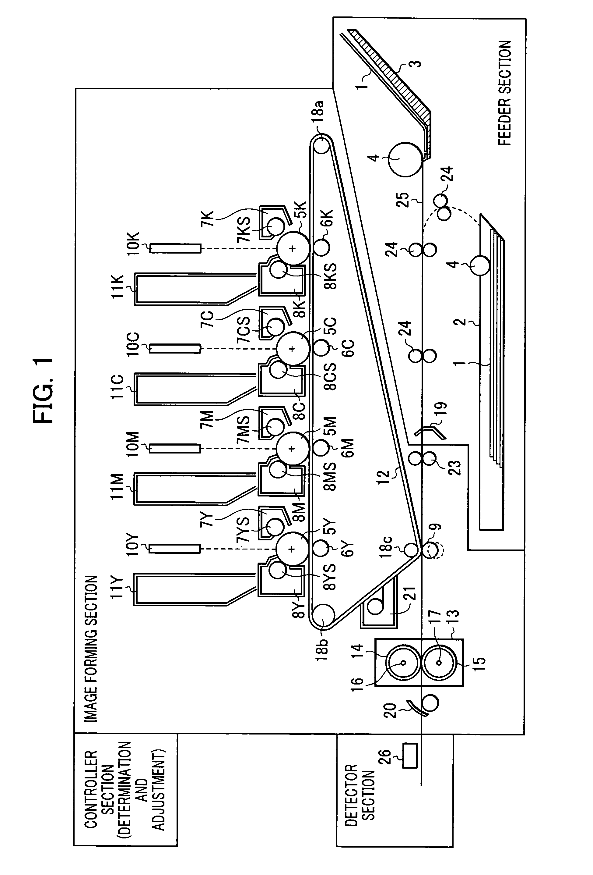
[0031]FIG. 1 is a diagram of a color image forming device according to a first embodiment of the present invention. In the first embodiment of the present invention, a media feeder is initially selected and a print medium on which a test pattern is to be printed is fed from the selected media feeder.
[0032]The color image forming device forms an electrostatic latent image for each color with exposure light based on image data in an image forming section, and then converts it to a visible image, transfers the color visible image to a print medium, and then fuses the image.
[0033]In the image forming section, stations for respective development colors are arranged. Each station includes a photoconductor drum 5, a charger 7, a developer 8, a laser scanner 10, and a toner cartridge 11. In this embodiment, the development colors are yellow (Y), magenta (M), cyan (C), and black (K). Since a station is provided for each color, four of each above-described component are provided. Therefore, t...
second embodiment
[0050]The present invention includes various embodiments that are consistent with the spirit and scope of the invention. For example, in a second embodiment, the present invention is applied to a color image forming device capable of automatic duplex printing. In duplex printing, an image is printed on both sides of the print medium. Specifically, an image is transferred to a first-side of the print medium and is fused, and then is delivered to a switchback mechanism (not shown). By the switchback mechanism (duplex printing unit), a surface of the print medium is turned over and is subsequently fed to the duplex path. After an image is transferred to a second-side of the print medium and is fused, the print medium is output from the device. After an image is formed on the second side of the print medium, the image forming device allows the print medium to be fed from the duplex path by selecting “duplex” as one of the feeders. That is, for the color image forming device capable of a...
third embodiment
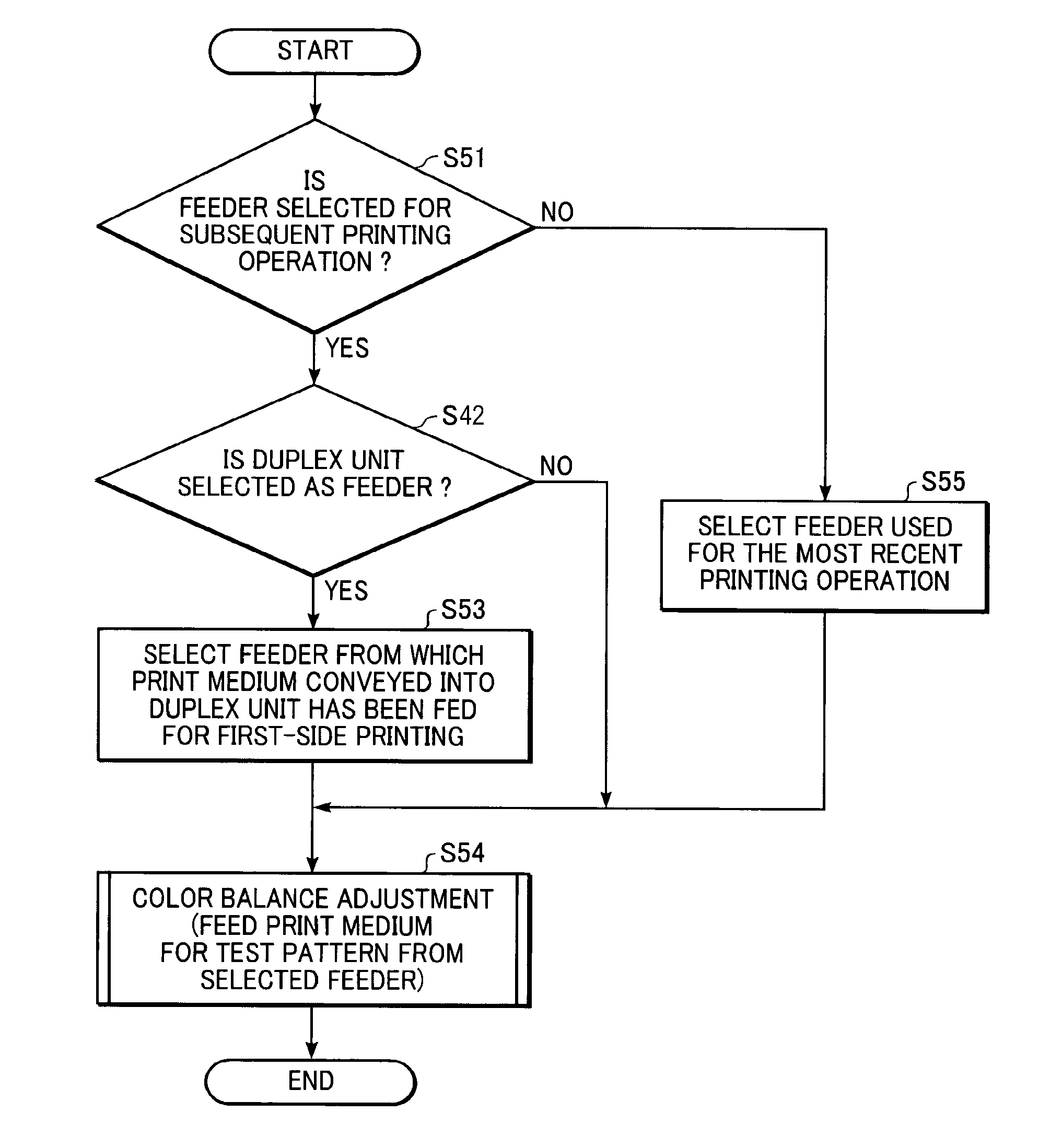
[0055]According to a third embodiment of the present invention, the last feeder used is stored in memory. If a feeder for printing is not selected, the stored last feeder is employed to feed the print medium.
[0056]FIG. 5 is a flow chart for performing color adjustment in accordance with the third embodiment of the present invention. The descriptions of processes in FIG. 5 identical to those in FIG. 4 are omitted.
[0057]At step S51, it is determined whether a feeder is selected for subsequent printing operation. If it is not selected, the process proceeds to step S55. At step S55, the feeder that was last used for printing is selected for feeding the print medium.
[0058]At step S54, the print medium for test pattern printing is fed from the selected feeder for subsequent printing, which is determined at step S51, the feeder determined at step S53, from which the print medium conveyed in the duplex printing unit after first-side printing has been fed, or the feeder determined in step S5...
PUM
| Property | Measurement | Unit |
|---|---|---|
| color balance | aaaaa | aaaaa |
| color | aaaaa | aaaaa |
| optical density | aaaaa | aaaaa |
Abstract
Description
Claims
Application Information
 - R&D
- Intellectual Property
- Life Sciences
- Materials
- Tech Scout
- Unparalleled Data Quality
- Higher Quality Content
- 60% Fewer Hallucinations
Browse by: Latest US Patents, China's latest patents, Technical Efficacy Thesaurus, Application Domain, Technology Topic, Popular Technical Reports.
© 2025 PatSnap. All rights reserved.Legal|Privacy policy|Modern Slavery Act Transparency Statement|Sitemap|About US| Contact US: help@patsnap.com