Volumetric pump with reciprocated and rotated piston

a volumetric pump and piston technology, applied in the direction of piston pumps, positive displacement liquid engines, liquid fuel engines, etc., can solve the problem and achieve the effect of increasing the cost of the pumping mechanism

Inactive Publication Date: 2011-02-15
SWISSINNOV PROD SARL
View PDF16 Cites 52 Cited by
  • Summary
  • Abstract
  • Description
  • Claims
  • Application Information

AI Technical Summary

Benefits of technology

[0003]GB 2060131, U.S. Pat. Nos. 4,767,399 and 4,850,980 disclose a pumping mechanism device whose suction and propulsion phases are achieved by means of a bidirectional linear movement of a piston inside a chamber. Unlike US 2004/101426, such pumping mechanism has

Problems solved by technology

Accordingly, the movement of the valve as well as its synchronization with the pist

Method used


Image

  • Volumetric pump with reciprocated and rotated piston
  • Volumetric pump with reciprocated and rotated piston
  • Volumetric pump with reciprocated and rotated piston

Examples


third embodiment

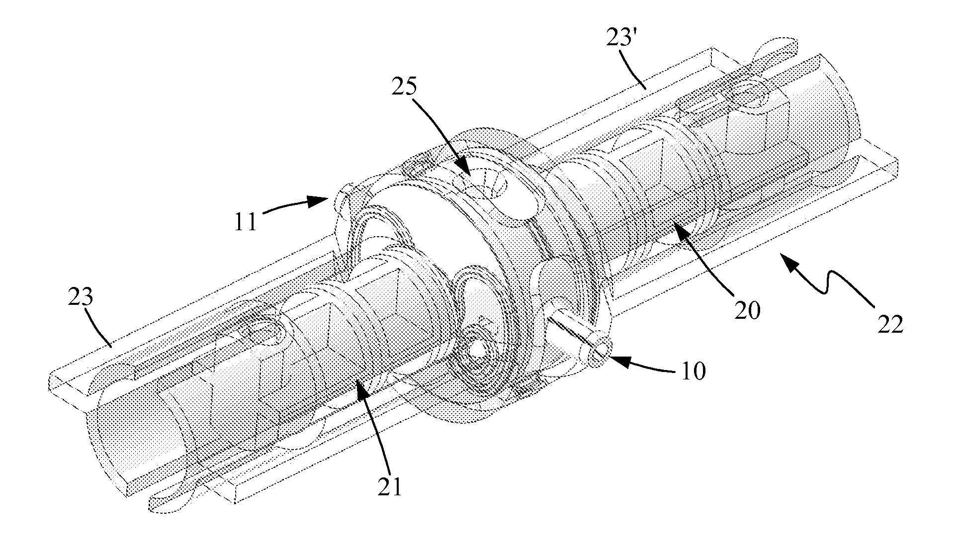
[0045]In the third embodiment, (FIGS. 9 to 15), a first and a second piston (20, 21) are fixedly positioned opposite to each other inside a hollow cylindrical mobile housing (22) as shown by FIG. 9. Said housing (22) is made up of two identical cylindrical parts (23, 23′) assembled end-to-end facing each other. A disc (24) (FIGS. 10a, 11, 11a) comprising the inlet and outlet ports (10, 11) located preferably laterally at 180° from each other and a hole (25) on its underneath part (FIG. 9a), is mounted midway inside said housing (22) between the two cylindrical parts (23, 23′). Such assembling creates a first and a second chamber (26, 26′) (FIG. 12b, 14b). The disc (24) is angularly movable relative to the housing (22) formed by parts (23, 23′).
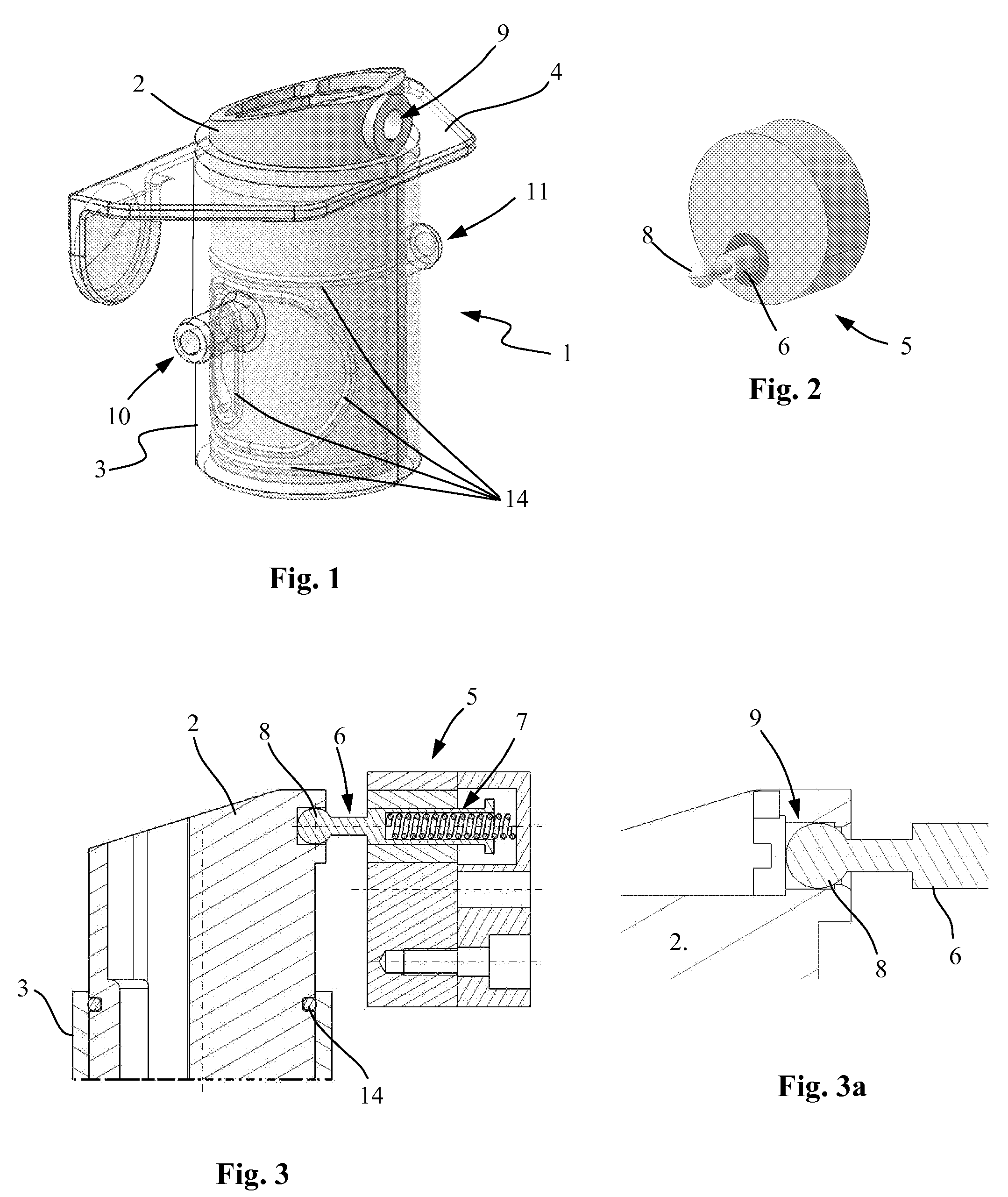
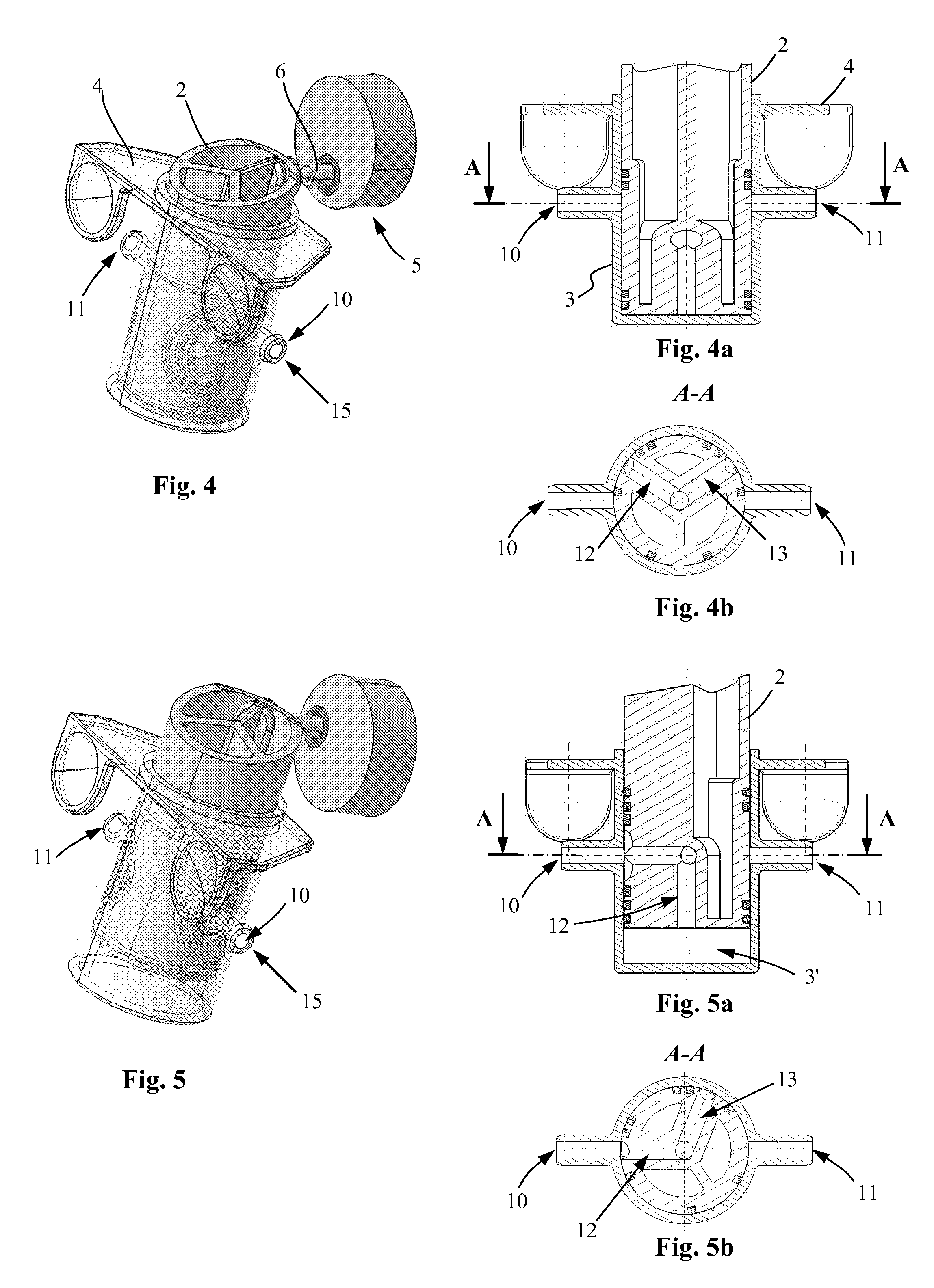
first embodiment

[0046]A shaft (not shown) is inserted into the hole (25), said shaft being mounted on a rotor (5), as described in the invention, for transmitting to the disc (24) a combined bi-directional linear and angular movement.

[0047]Such movement of the disc (24) causes the cylindrical housing (22) to slide back and forth following the axis of the two pistons (20, 21) while closing the inlet and outlet ports (10, 11) so as to ensure on the one hand an alternate sucking of the fluid (15) from the inlet port (10) to respectively the first and second chamber (26, 26′) and on the other hand an alternate expelling of the fluid (15) from respectively the first and second chambers (26, 26′) to the outlet port (11).

[0048]The optimum synchronization of the suction and propulsion phases between the two chambers (26, 26′) is achieved by a first and a second T-shaped channel (27, 27′) located inside the disc (24) and in its inlet / outlet as shown by FIG. 11a. Channels (27, 27′) connect alternately the in...


PUM


Abstract

A volumetric pump (1) comprising a piston (2) and a cylindrical chamber (3), contains an inlet port (10) and an outlet port (11). The piston (2) is actuated by a rotor (5) bearing an eccentric shaft (6). The shaft (6), being connected to the piston (2), causes the piston to slide back and forth inside the cylinder chamber (3) while having a bidirectional angular movement. The instroke of the piston (2) sucks a fluid (15) from the inlet port (10) through a first channel (12) into the pump chamber (3), the fluid being propelled through a second channel (13) to the outlet port (11) during the outstroke of the piston (2). The inlet (10) and outlet port (11) are opened and closed alternatively by the bidirectional angular movement of the piston (2) which acts as a valve for the inlet and outlet ports (10, 11).

Description

BACKGROUND OF THE INVENTION[0001]The present invention concerns a volumetric pump which may be used in different fields such as medical drug or fluid delivery (infusion Pump, IV pump, enteral pump, parenteral pump) or food, chemical or other industry, for example in conjunction with a compressor or an internal combustion engine.[0002]Piston pumps with fluid modules are already part of the prior art. US 2004 / 101426 discloses a device comprising a cylindrical piston chamber whose upper and lower ends' profile have a specific gradient, said piston chamber containing a rotatable and axially movable pump piston. The profile of the upper and lower end surfaces of the piston has been determined to run concomitantly in contact with the respective two end surfaces of the chamber as the piston rotates. This rotation causes the piston to move alternately upwards and downwards permitting one-way suction and one-way propulsion of a fluid respectively into and out of the pump chambers. The rotati...

Claims


Application Information

Patent Timeline
IPC IPC(8): F04B37/00
CPCF04B7/06F04B9/02F04B9/04F04B19/022F04C9/00F04B7/04F01C9/00
Inventor NAVARRO, THIERRY
Owner SWISSINNOV PROD SARL
Why Eureka
Try Eureka