Fixing device and image forming apparatus

a technology of fixing device and image forming apparatus, which is applied in the direction of electrographic process apparatus, instruments, optics, etc., can solve the problems of large temperature differences between the pass area and the non-pass area, the difficulty of the pressure roller in transporting heat, and the inability to equalize the temperature of the pressure roller in the axial direction, so as to improve the product quality and the durability of the apparatus

Inactive Publication Date: 2011-04-12
KONICA MINOLTA BUSINESS TECH INC
View PDF27 Cites 15 Cited by
  • Summary
  • Abstract
  • Description
  • Claims
  • Application Information

AI Technical Summary

Benefits of technology

[0006]Accordingly, an object of the present invention is to provide a fixing device and an image forming apparatus which are capable of suppressing temperature increases in the non-pass areas in continued feeding of a small-size recording sheet to thereby reduce temperature differences between sheet-pass area and non-pass areas, thus preventing degradation in image quality (fixability) of small-size recording sheets and moreover preventing thermal deterioration of the fixing roller and the pressure roller.
[0012]Therefore, temperature increases in the non-pass areas in continued feeding of small-size sheets of the recording material can be suppressed, so that temperature differences between the sheet-pass area and the non-pass areas can be reduced. Thus, there is no need for lowering the heating temperature of the heating section to lower the temperature of the non-pass areas, so that degradation in image quality (fixability) of the small-size recording material is prevented. Also, since temperature increases in the non-pass areas can be suppressed, thermal deterioration of the fixing-side rotating member and the pressing-side rotating member can be prevented.
[0015]According to the image forming apparatus of this invention, since the fixing device is included therein, product quality and apparatus durability can be improved.

Problems solved by technology

However, in this conventional fixing device, since the pressure roller has a core metal, a sponge layer, an elastic layer and a PFA tube in this order from inside to outside, it is difficult for the pressure roller to transport heat which has been transferred directly from the fixing roller to the pressure roller.
As a result, it has been the case that temperature of the pressure roller in its axial direction cannot be equalized.
As a consequence, temperature of non-pass areas in continued feeding of small-size recording sheets is increased, causing larger temperature differences between the pass area and the non-pass areas.
This involves a need for lowering the heating temperature of the heater to lower the temperature of the non-pass areas, posing a problem of degradation in image quality (fixability) of small-size recording sheets.
Furthermore, because of such temperature increases in the non-pass areas, there has been a problem of thermal deterioration of the fixing roller and the pressure roller.

Method used


Image

  • Fixing device and image forming apparatus
  • Fixing device and image forming apparatus
  • Fixing device and image forming apparatus

Examples


first embodiment

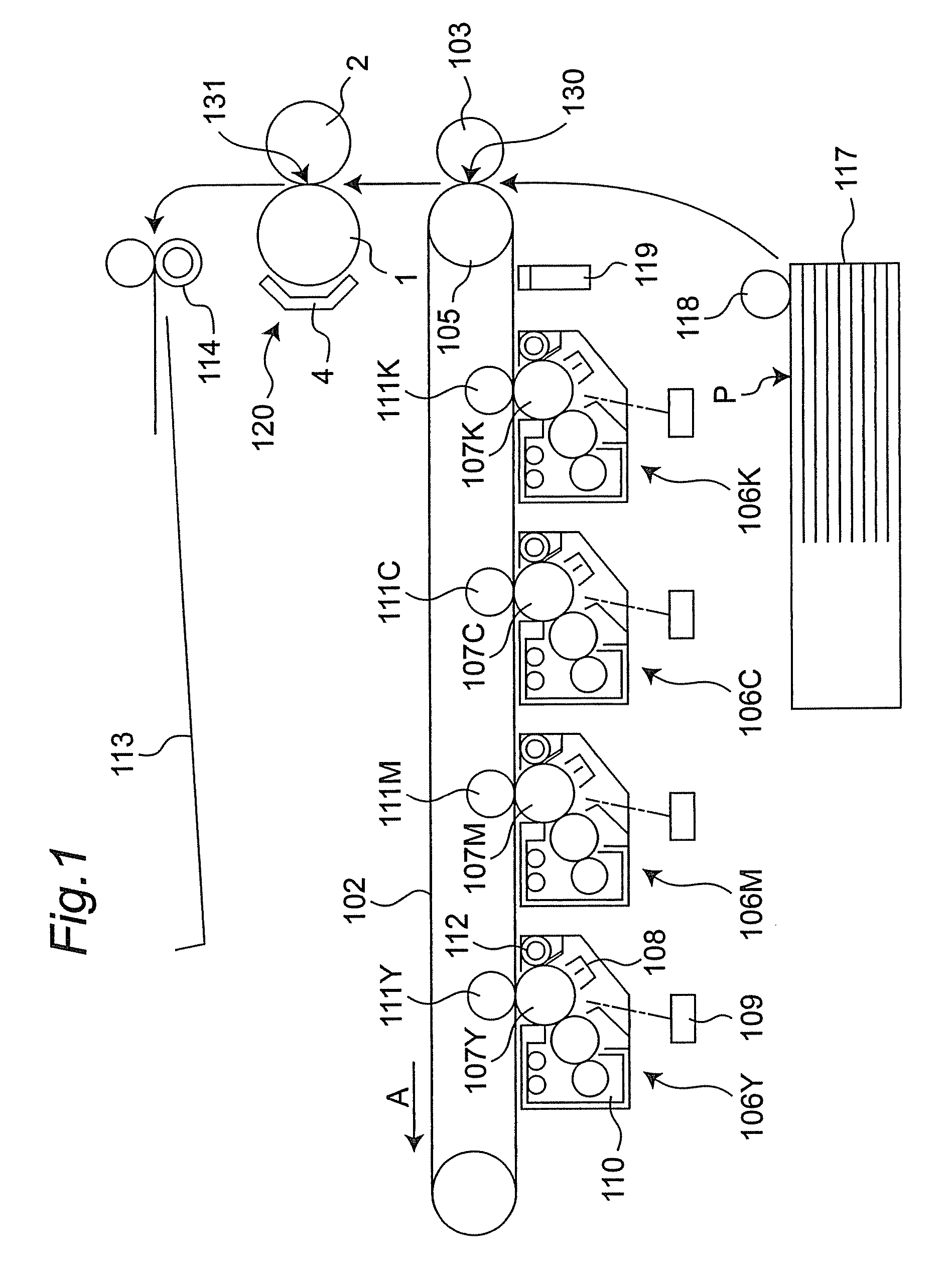
[0027]FIG. 1 shows a simplified structural view of an image forming apparatus of the invention. The image forming apparatus, shown as a color printer, has an intermediate transfer belt 102 as a belt member at a generally center of the inside of the apparatus. Under a lower horizontal portion of the intermediate transfer belt 102, four image forming units 106Y, 106M, 106C, 106K corresponding to yellow (Y), magenta (M), cyan (C) and black (K) colors, respectively, are placed in array along the intermediate transfer belt 102. The image forming units 106Y, 106M, 106C, 106K have photoconductor drums 107Y, 107M, 107C, 107K, respectively.

[0028]A charger 108, a print head unit 109, a developer unit 110, a primary transfer roller 111Y, 111M, 111C, 111K, and a cleaner 112 are placed around each of the photoconductor drums 107Y, 107M, 107C, 107K in this order along the rotational direction of the drums. The primary transfer rollers 111Y, 111M, 111C, 111K confront the photoconductor drums 107Y,...

second embodiment

[0070]FIG. 6 shows a second embodiment of the fixing device of the invention. This second embodiment differs from the first embodiment in terms of the construction of the pressure roller.

[0071]As shown in FIG. 6, a pressure roller 2A, as compared with the pressure roller 2 of FIG. 4, has a high thermal-conduction elastic layer 25 between the metal layer 23 and the mold releasing layer 24. It is noted here that like reference signs denote like component members as in the first embodiment, and so their description is omitted.

[0072]The high thermal-conduction elastic layer 25 is larger in thermal conductivity than the low thermal-conduction elastic layer 22. The high thermal-conduction elastic layer 25 is formed of silicone rubber having a thermal conductivity of 0.5 W / m·° C. The high thermal-conduction elastic layer 25 is 150 to 300 μm thick. The high thermal-conduction elastic layer 25 functions to more equalize the temperature of the pressure roller 2A in its axial direction.

[0073]N...


PUM


Abstract

A fixing device has a fixing roller, a pressure roller, an electromagnetic-induction heating section, and a heat pipe. The pressure roller has a metal layer, so that heat transferred directly from the fixing roller to the pressure roller is thermally transported by the metal layer of the pressure roller, whereby temperature of the pressure roller in its axial direction can be equalized.

Description

CROSS-REFERENCE TO RELATED APPLICATION[0001]This application is based on application No. 2008-159286 filed in Japan, the entire content of which is hereby incorporated by reference.TECHNICAL FIELD[0002]The present invention relates to a fixing device for use in image forming apparatuses such as copiers, printers and facsimile machines, and also relates to an image forming apparatus having such a fixing device.BACKGROUND ART[0003]Conventionally, there is a fixing device including a fixing roller, a pressure roller and a heater (see JP 8-54798 A). The fixing roller is heated by the heater. The fixing roller and the pressure roller heat and pressure a recording sheet to fix toner on the sheet. The pressure roller has a core metal, a sponge layer, an elastic layer and a PFA (tetrafluoroethylene perfluoroalkoxy vinyl ether copolymer) tube in this order from radially inside to outside.[0004]However, in this conventional fixing device, since the pressure roller has a core metal, a sponge l...

Claims


Application Information

Patent Timeline
Patent Type & Authority Patents(United States)
IPC IPC(8): G03G15/20
CPCG03G15/206G03G15/2042G03G15/2039
Inventor URANO, ETSUAKI
Owner KONICA MINOLTA BUSINESS TECH INC
Why Eureka
Try Eureka