Automated medical liquid filling system and method

a technology of medical liquid and automatic filling, which is applied in the field of automatic filling of medical liquid, can solve the problems of cross-flow between the various sections of the tubing, the deformation of the spring force of the anvil, and the inability to accurately fill the medical liquid

Active Publication Date: 2011-08-16
BAXTER ENGLEWOOD
View PDF16 Cites 36 Cited by
  • Summary
  • Abstract
  • Description
  • Claims
  • Application Information

AI Technical Summary

Benefits of technology

[0007]Another objective of embodiments of the present invention may be to facilitate an optimal rate of medical liquid flow.
[0034]In yet another aspect, the inventive method may include the step of automatically controlling the piston drive member to automatically adjust a force applied by the piston drive member to the piston of the disposable during at least a portion of at least one of the using (e.g., piston retraction) and employing (e.g., piston advancement) steps. In turn, the automatic controlling step may provide for the maintenance of the applied force within a predetermined range, wherein a predetermined maximum of the predetermined range corresponds with a predetermined maximum desired fluid pressure for the disposable. Relatedly, a predetermined minimum of the predetermined range may be established to be within a given relatively small percentage of the predetermined maximum (e.g., less than 10%) so that the medical liquid flow rate into and / or out of the disposable is maximized.

Problems solved by technology

While peristaltic pumps are operable to deliver medical liquids, peristaltic pumps suffer in that the flexible tubing may move and / or twist during operation, the flexible tubing may deform over time from repeated compression and expansion, variable inlet and outlet pressure may be experienced, pulsatile flow with undesired flow reversal may occur, and / or the spring forces associated with the anvils may degrade over time.
Such factors may potentially result in the dispensing of inaccurate volumes of medical liquids.
As such, systems employing such peristaltic pumps typically require calibration at the outset of each medical liquid filling procedure.
The tubing deformation may also lead to seepage around the anvils, thereby leading to cross-flow between the various sections of the tubing.
Peristaltic pumps also are limited by the intake speed of rotation.
If the inlet pressure is too high in relation to the vapor pressure of the liquid, a portion of the liquid may evaporate upon intake, which is undesirable for many reasons (e.g., the dispensing of inaccurate liquid volumes).
Thus, the maximum rate of fluid flow speed may be substantially less than desired due to the inherent tying of the inlet pressure to the outlet pressure in the peristaltic pump.

Method used


Image

  • Automated medical liquid filling system and method
  • Automated medical liquid filling system and method
  • Automated medical liquid filling system and method

Examples


Embodiment Construction

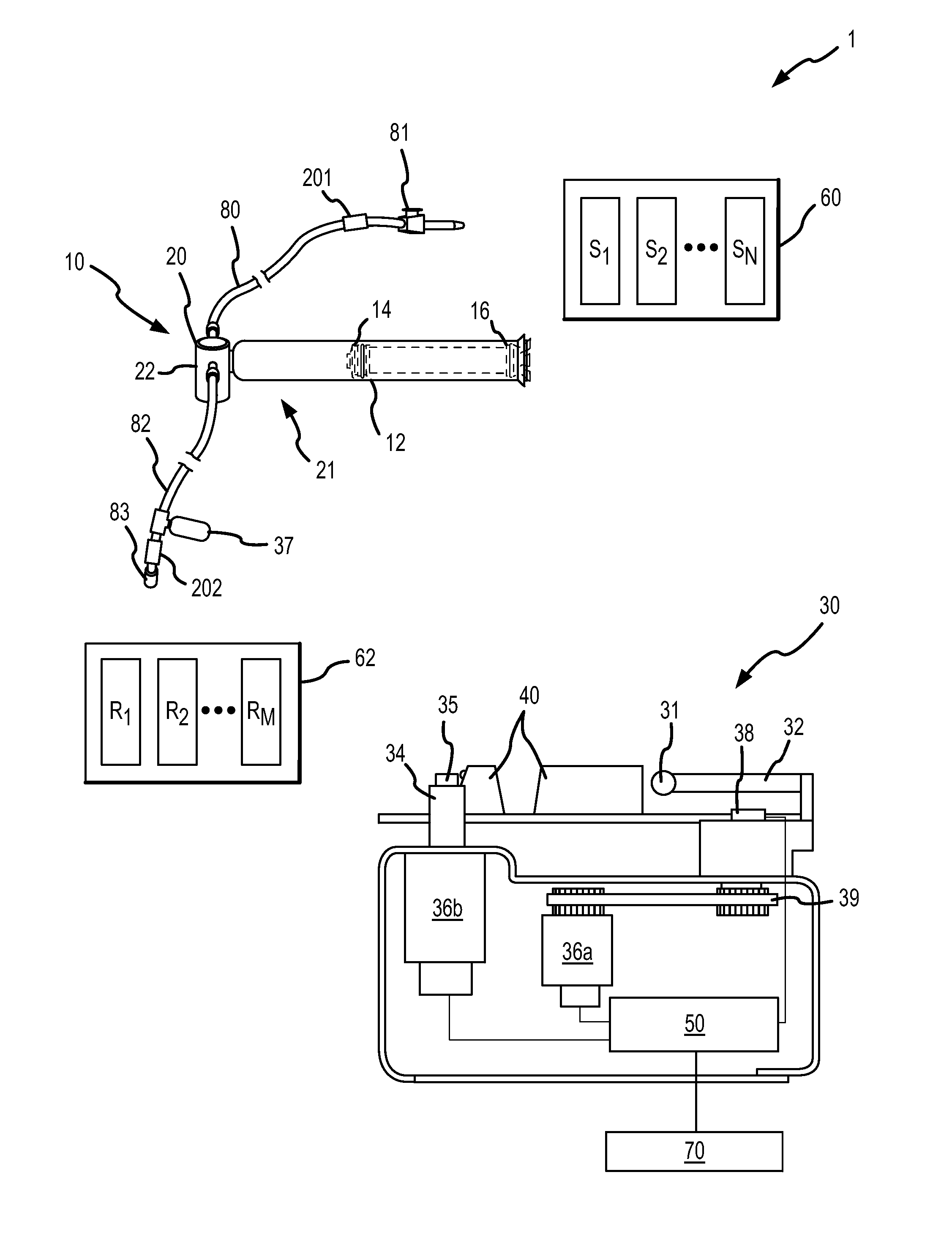
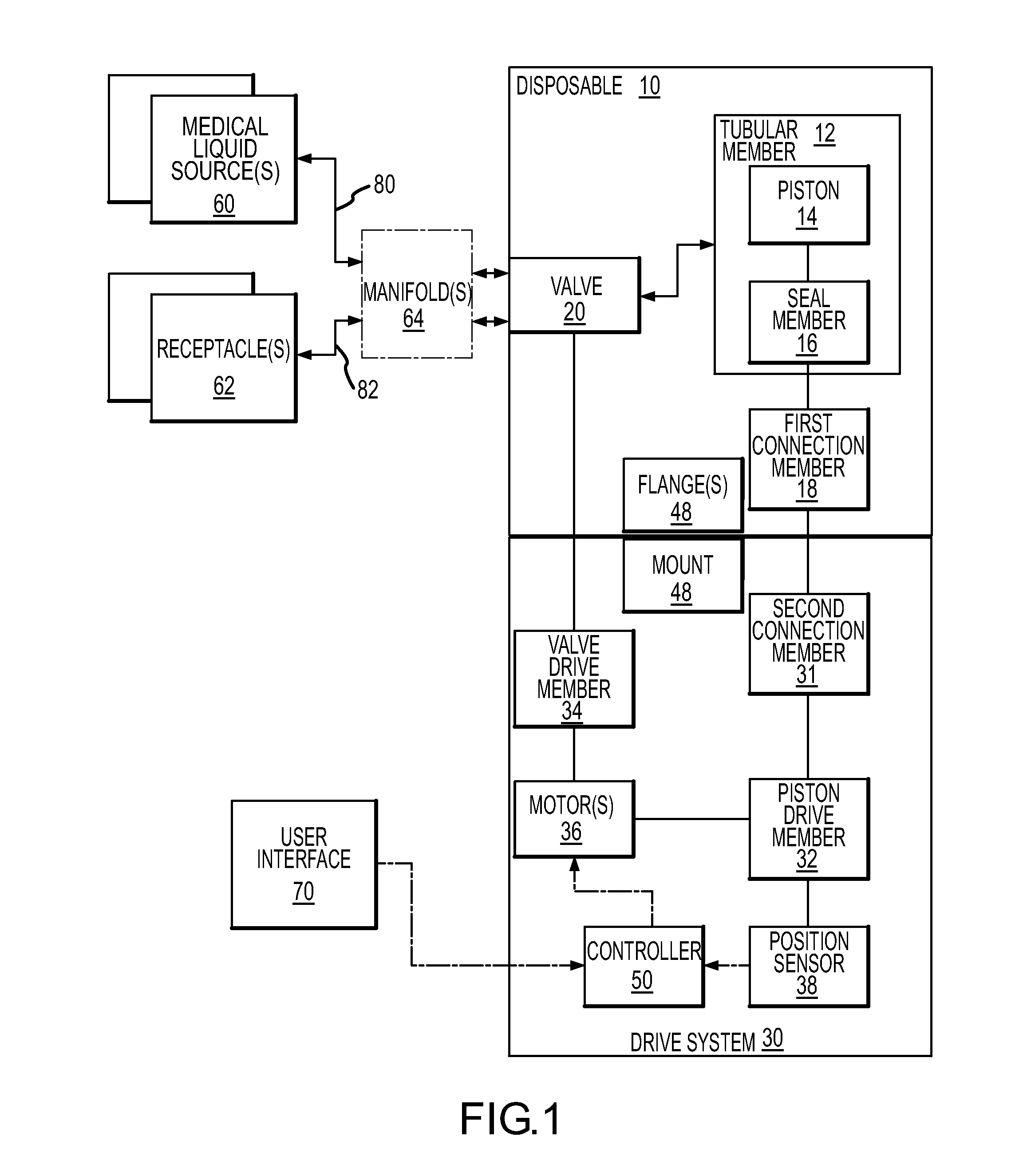
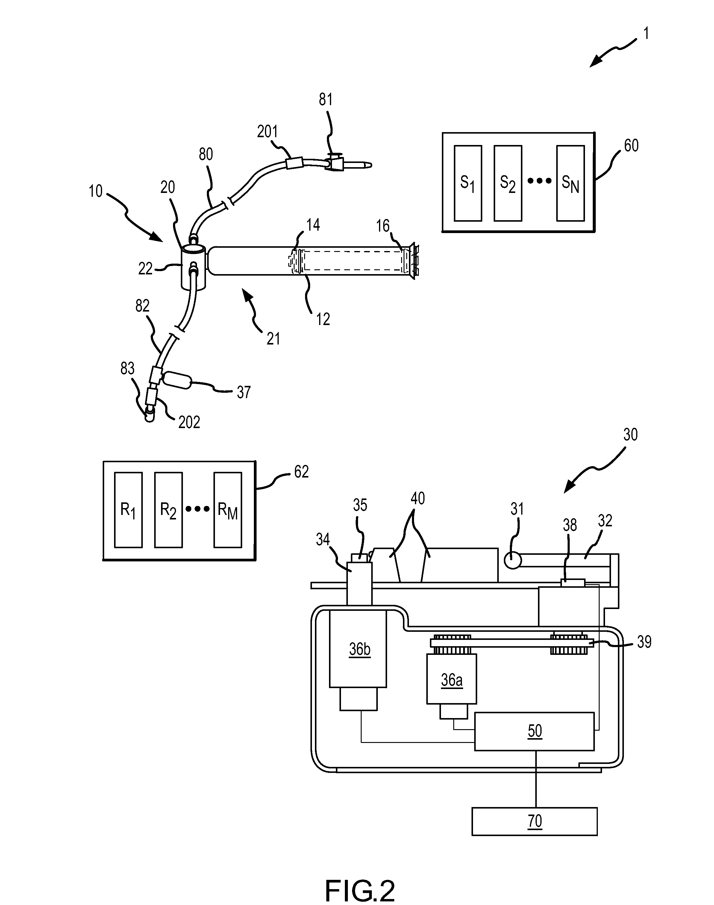
[0084]Reference is now made to FIGS. 1 and 2, which illustrate one embodiment of a medical liquid filling system of the present invention. The medical liquid filling system 1 generally includes a disposable 10, a drive system 30, one or more medical liquid sources 60 (“medical liquid source(s)”) and one or more receptacles 62 (“receptacle(s)”). The disposable 10 may be selectively engageable and disengageable with the drive system 30 via flanges 48 and a mount 40. The medical liquid source(s) 60 may be fluidly interconnectable to the disposable 10 via a first fluid line 80 and an optional manifold 64 (e.g., included when multiple medical liquid sources are provided). Similarly, the receptacle(s) 62 may be fluidly interconnectable to the disposable 10 via a second fluid line 82 and the optional manifold 64.

[0085]The disposable 10 may include a housing 21 that may include a valve housing 22 and a tubular member 12. The housing 21 may be a single piece (e.g., a one piece molded part) o...


PUM

PropertyMeasurementUnit
pressureaaaaaaaaaa
pressureaaaaaaaaaa
pressureaaaaaaaaaa

Abstract

A medical liquid filling system and associated methods are provided, the system comprising a disposable and a drive system. The disposable includes a tubular member and a piston slidably disposed within the tubular member for retraction and advancement within at least a first portion of the tubular member. The disposable may include a seal member for sealing the first portion of the tubular member and may be interconnected to the piston for co-movement therewith. The drive system may include a piston drive member selectively interconnectable to the piston for driven advancement and retraction of the piston within the tubular member. The drive system may be interconnected to a controller, which may be operable to automate or semi-automate various filling operations. A user interface may be interconnected to the controller for providing input of various system operation parameters, which may be communicated to the controller to facilitate automated or semi-automated operation of the filling system.

Description

RELATED APPLICATIONS[0001]This application claims priority from U.S. Provisional Patent Application Ser. No. 60 / 742,114, filed Dec. 2, 2005, entitled “Improved Automated Liquid Filling System and Method,” and the entire disclosure of which is incorporated by reference in its entirety herein.FIELD OF THE INVENTION[0002]The present invention relates to systems, apparatus and methods for automated filling of medical liquids. More particularly, embodiments of the present invention relate to systems, apparatus and methods for automated filling of medical liquids using a disposable syringe-like apparatus interconnectable with a drive system, a medical liquid source and a plurality of receptacles. The system, apparatus and methods may be employable to flow medical liquids to a plurality of receptacles to provide, for example, liquid medication in a desired volume.BACKGROUND OF THE INVENTION[0003]Providing medical liquids in a sterile and precise manner is desirable in many instances. For e...

Claims


Application Information

Patent Timeline
Patent Type & Authority Patents(United States)
IPC IPC(8): B65B3/04
CPCB65B3/003A61J2001/2065A61M2005/3114A61M2209/045A61M2207/00A61J1/20A61J1/2065
Inventor RANALLETTA, JOSEPH VINCENTHUTCHINS, IV, LOREN HAVENERAUMILLER, JOSHUA NATHANOLICHNEY, MICHAEL DICKSON
Owner BAXTER ENGLEWOOD
Why Eureka
Try Eureka