Wind turbine, tower and method for fabricating the same

a technology for wind turbines and towers, which is applied in the field of wind turbine towers, can solve the problems of increased blade cost and weight, undesirable blades striking the tower during the turbine operation, and increased stress levels in the tower, so as to increase static clearance, reduce diameter, and increase the effect of static clearan

Inactive Publication Date: 2011-08-16
GENERAL ELECTRIC CO
View PDF14 Cites 7 Cited by
  • Summary
  • Abstract
  • Description
  • Claims
  • Application Information

AI Technical Summary

Benefits of technology

[0004]In one aspect of the present invention, a wind turbine is provided. The wind turbine includes a rotor having one or more blades and a rotor radius distance approximately equal to the distance measured from a centerline of the rotor to a tip of one of the blades. The tower has one or more tower sections, including a first tower section having a generally cylindrical or frusto-conical shape. The first tower section has at least one first diameter. A reduced diameter tower section is connected to the first tower section, and has a waist portion with at least one second diameter that is smaller than the first diameter. At least a portion of the reduced diameter tower section having the second diameter is located about one rotor radius distance from the centerline of the rotor, and the reduced diameter section provides increased static clearance to the tip of the blades.
[0005]In another aspect of the present invention, a wind turbine tower for supporting a rotor is provided. The rotor has one or more blades and a rotor radius distance approximately equal to the distance measured from a centerline of the rotor to a tip of one of the blades. The wind turbine tower has one or more tower sections, including a first tower section having a generally cylindrical or frusto-conical shape. The first tower section has at least one first diameter. A reduced diameter tower section is connected to the first tower section, and has a waist portion with at least one second diameter that is smaller than the first diameter. At least a portion of the reduced diameter tower section having the second diameter is located about one radius distance from the centerline of the rotor. The reduced diameter section provides increased static clearance to the tip of the blades.

Problems solved by technology

It would be undesirable to have the blades strike the tower during operation of the turbine.
Blade cost and weight increase as additional materials are required to stiffen the blades.
Stiffer blades can also result in higher stress levels in the tower.

Method used


Image

  • Wind turbine, tower and method for fabricating the same
  • Wind turbine, tower and method for fabricating the same
  • Wind turbine, tower and method for fabricating the same

Examples


Embodiment Construction

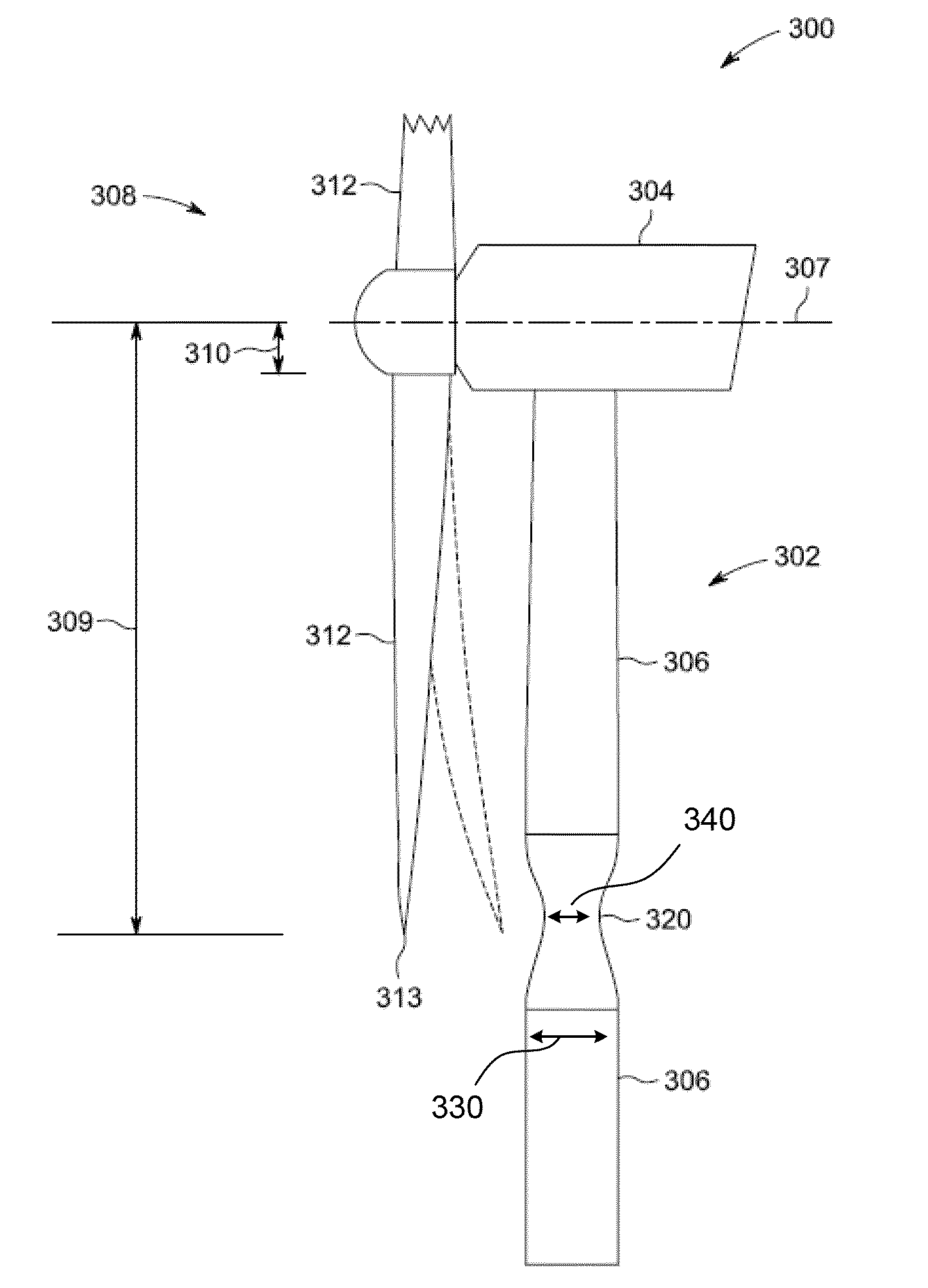
[0013]The following detailed description describes a wind turbine, wind turbine tower and method for fabricating or making a tower by way of example and not by way of limitation. The description enables one of ordinary skill in the art to make and use the disclosure, and the description describes several embodiments of the disclosure, including what is presently believed to be the best mode of carrying out the disclosure. The disclosure is described herein as being applied to an exemplary embodiment, namely, a wind turbine tower. However, it is contemplated that this disclosure has general application to towers in a broad range of systems and in a variety of applications other than wind turbines.

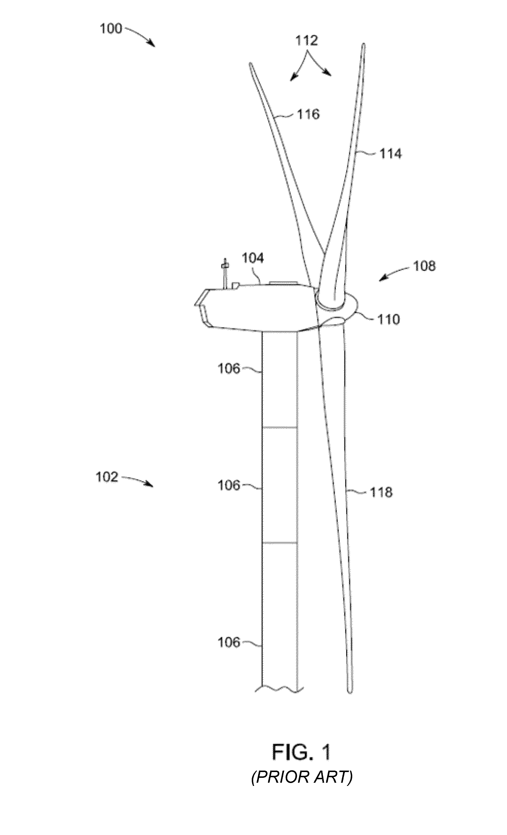
[0014]FIG. 1 is a side elevation view of an exemplary wind turbine 100. In the exemplary embodiment, wind turbine 100 is a horizontal axis wind turbine. Alternatively, wind turbine 100 may be a vertical axis wind turbine. Wind turbine 100 includes a tower 102 erected from a foundation (not s...


PUM

PropertyMeasurementUnit
diameteraaaaaaaaaa
diameteraaaaaaaaaa
distanceaaaaaaaaaa

Abstract

A wind turbine, tower and method for making same are provided. The wind turbine includes a rotor having one or more blades and a rotor radius distance approximately equal to the distance measured from a centerline of the rotor to a tip of one of the blades. The tower has one or more tower sections, including a first tower section having a generally cylindrical or frusto-conical shape. The first tower section has at least one first diameter. A reduced diameter tower section is connected to the first tower section, and has a waist portion with at least one second diameter that is smaller than the first diameter. At least a portion of the reduced diameter tower section having the second diameter is located about one rotor radius distance from the centerline of the rotor, and the reduced diameter section provides increased static clearance to the tip of the blades.

Description

BACKGROUND OF THE INVENTION[0001]The subject matter described herein relates generally to wind turbines and, more particularly, to a wind turbine tower and a system and method for fabricating or making a wind turbine tower.[0002]Many known wind turbines include a tower and a rotor mounted on the tower via a nacelle. The rotor includes a number of blades that facilitate converting wind energy into rotational energy. The rotor typically drives a generator through a gearbox via a rotor shaft, and the gearbox steps up the inherently low rotational speed of the rotor shaft such that the generator can convert the mechanical energy to electrical energy.[0003]The blades of the rotor are configured to have a specific clearance between their lowest point of travel and the tower. It would be undesirable to have the blades strike the tower during operation of the turbine. However, known solutions to this problem include tilting the rotor up at a predetermined angle and / or using blades with a pr...

Claims


Application Information

Patent Timeline
Patent Type & Authority Patents(United States)
IPC IPC(8): F03D11/04
CPCF03D11/04Y02E10/721Y02E10/728Y10S416/06Y10T29/49229Y10T29/49631Y10T29/49236Y10T29/49316F05B2270/17F03D13/20Y02E10/72Y02P70/50
Inventor NIES, JACOB JOHANNESMALIK, TAHIR HASSAN
Owner GENERAL ELECTRIC CO
Why Eureka
Try Eureka