Blade structure of torque converter and method for producing blade structure of torque converter

a technology of torque converter and blade structure, which is applied in the direction of marine propulsion, vessel construction, gearing, etc., can solve the problems of low working efficiency and process in jp9-042413, and achieve the effect of accurately setting, shortening assembly or working time, and reducing production costs

Inactive Publication Date: 2012-04-17
JATCO LTD
View PDF10 Cites 1 Cited by
  • Summary
  • Abstract
  • Description
  • Claims
  • Application Information

AI Technical Summary

Benefits of technology

[0004]In the above method to produce the blade member in JP9-042413, it could be possible to shorten the assembly or working time. However, in JP9-042413, the one rectangular steel plate, in which the plurality of stamped blades are formed, is curved so that its shape becomes a ring shape. More specifically, upper and lower sides of the rectangular steel plate are respectively folded or bent by mutually different fold amounts, then a curved blade member (i.e. a ring shaped blade member) is produced. Regarding this folding process, the fold amounts of the upper and lower sides of the rectangular steel plate are accurately set, and each connecting portion between the stamped blades is folded by the accurately set amount by a computer-controlled robot. Thus, a sophisticated folding or bending process is required. In addition, this folding process has to be carried out for each of the connecting portions of the blade. In other words, this folding operation has to be performed for the each connecting portion one by one. Hence, although the production time of the blade might be shortened through the method of JP9-042413, the process in JP9-042413 is inefficient and the working efficiency is not necessarily high.
[0005]It is therefore an object of the present invention to provide a blade structure, of a torque converter, where a plurality of blades are integrally formed with each other by a stamping process etc. and which can be easily and promptly produced.

Problems solved by technology

Hence, although the production time of the blade might be shortened through the method of JP9-042413, the process in JP9-042413 is inefficient and the working efficiency is not necessarily high.

Method used


Image

  • Blade structure of torque converter and method for producing blade structure of torque converter
  • Blade structure of torque converter and method for producing blade structure of torque converter
  • Blade structure of torque converter and method for producing blade structure of torque converter

Examples


Embodiment Construction

[0019]Embodiments of a blade structure and a blade structure-producing method will be explained below with reference to the drawings.

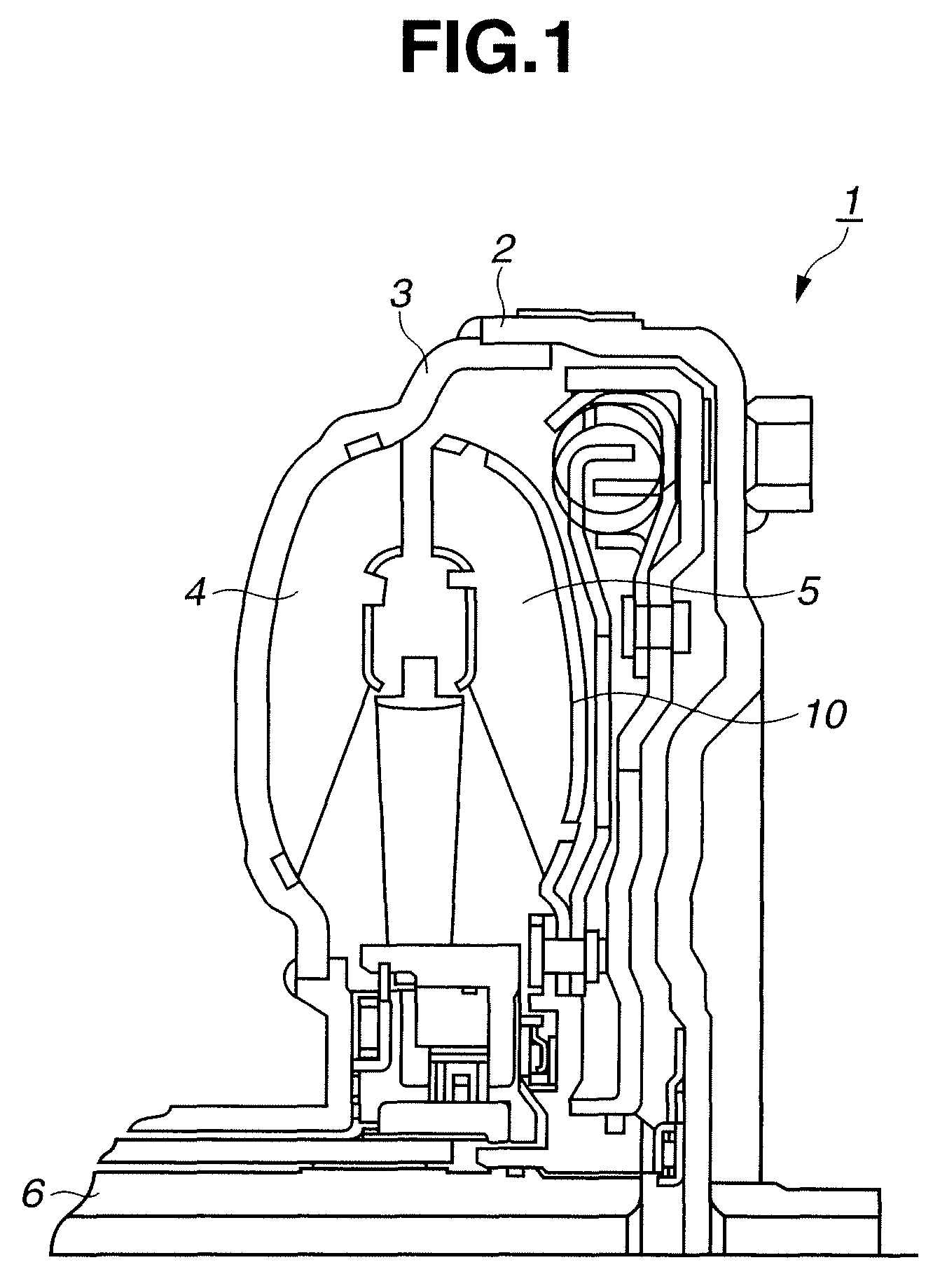
[0020]Now, a configuration of a torque converter 1 of the present invention will be explained with reference to FIG. 1. A torque converter 1 is a hydraulic coupling, which is installed between an engine and an automatic transmission of a vehicle.

[0021]Torque converter 1 has a front cover 2, a rear cover 3, a pump impeller 4 installed in an inner wall of rear cover 3, a turbine runner 5 facing pump impeller 4, and an output shaft 6. Rear cover 3 is fixed to front cover 2, and when front cover 2 rotates by rotation from the engine (not shown), rear cover 3 rotates together with front cover 2. On the other hand, when turbine runner 5 rotates, its rotation is transferred to the automatic transmission (not shown) through output shaft 6.

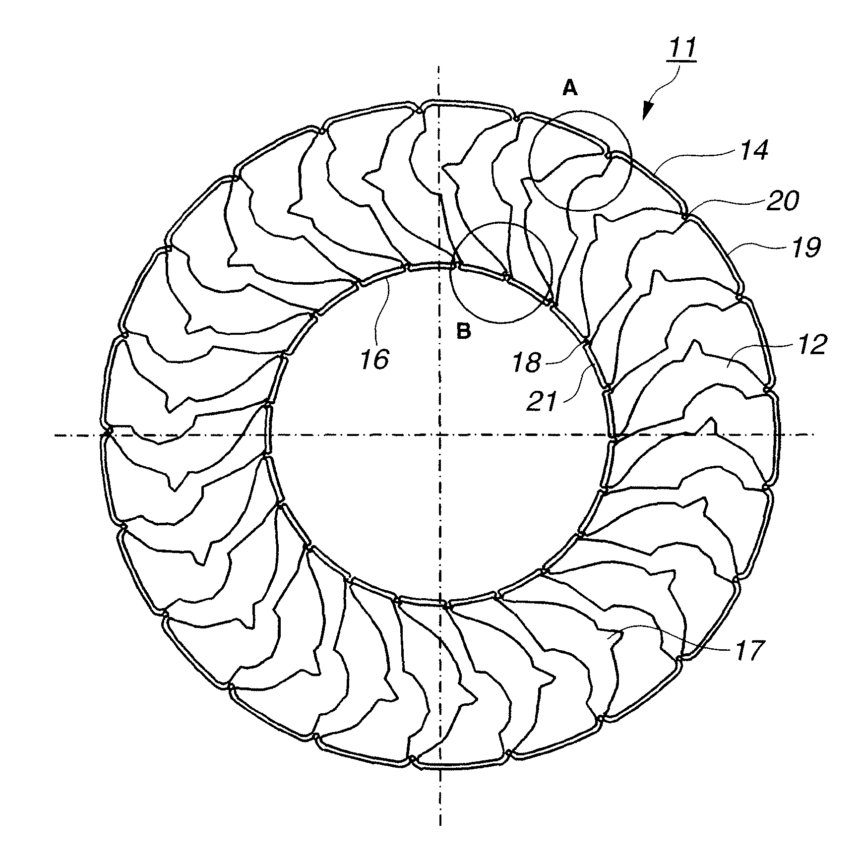
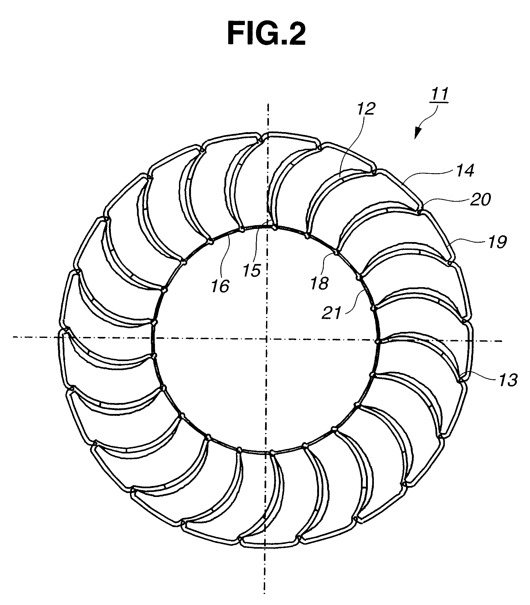
[0022]Turbine runner 5 has a substantially ring-shaped turbine shell (shell member) 10 and a blade structure 11 which is in...


PUM

PropertyMeasurementUnit
distanceaaaaaaaaaa
outer circumferenceaaaaaaaaaa
circumferenceaaaaaaaaaa

Abstract

A blade structure of a torque converter, having a plurality of blades, is produced according to processes. The processes has (a) stamping a plane plate into a first shape, the first shape has (i) the plurality of circumferentially arranged blades, (ii) ring-shaped first connecting portions, each of which integrally couples the adjacent blades together at an outer circumference side of the blade structure, and (iii) ring-shaped second connecting portions, each of which integrally couples the adjacent blades together at an inner circumference side of the blade structure, (b) curving a surface of the stamped blade, (c) inclining the blade at a predetermined angle with respect to the first and second connecting portions while inclining the first and second connecting portions, and (d) adjusting a distance between the adjacent blades and shrinking the first shape in a radial direction by the inclination of the first and second connecting portions.

Description

BACKGROUND OF THE INVENTION[0001]The present invention relates to a blade structure of a torque converter and a method for producing the blade structure of the torque converter.[0002]The torque converter has a plurality of bladed members (blades) in a fluid-filled shell for transferring power through the fluid. These blades are generally installed and fixed to the shell one by one. Thus this installation work is inefficient, and causes the increase in assembly time.[0003]For this problem, Japanese Patent Provisional Publication No. 9-042413 (hereinafter is referred to as “JP9-042413”) has disclosed a method for producing a blade member having a plurality of the blades which are integrally connected with each other by stamping the blades from one steel plate or sheet.SUMMARY OF THE INVENTION[0004]In the above method to produce the blade member in JP9-042413, it could be possible to shorten the assembly or working time. However, in JP9-042413, the one rectangular steel plate, in which...

Claims


Application Information

Patent Timeline
Patent Type & Authority Patents(United States)
IPC IPC(8): F16H41/26
CPCF16H41/28Y10T29/49336F16H41/26
Inventor SAITOU, KAZUMI
Owner JATCO LTD
Why Eureka
Try Eureka