GC-MS analysis apparatus

a technology of analysis apparatus and carrier gas, which is applied in the direction of specific gravity measurement, separation process, instruments, etc., can solve the problems of high cost, complicated and expensive manufacture and management of known apparatuses, and the addition of carrier gas and other gases, so as to achieve affordable costs

Inactive Publication Date: 2012-08-07
AGILENT TECH INC
View PDF28 Cites 8 Cited by
  • Summary
  • Abstract
  • Description
  • Claims
  • Application Information

AI Technical Summary

Benefits of technology

[0024]Advantageously, the interface section according to the present invention determines the necessary analyte molecular flow directed towards the section MS and the pumping capability required for the vacuum system can therefore result to be reduced with respect to the prior art devices, wherein substantially the whole flow coming from chromatographic column is sent to the MS section. This condition makes possible, for example, use of ionic vacuum pumps, which are, in general, structurally more simplified than vacuum systems based on turbomolecular pumps having a rotary mechanical structure and requiring complicated electronic control devices. Due to the vacuum system simplification, the consequent reduced weight and the lower electrical current absorption, it is advantageously possible to manufacture apparatuses, which are compact, transportable and battery-operated.

Problems solved by technology

The known apparatuses are complicated and expensive to manufacture and to manage, and require remarkable investments.
The supply of the carrier gas and other gases are added costs.
The permeation leaks devices have, a very unstable behaviour when the temperature changes (their value varies of about 3% per centigrade grade in case of temperature values around room temperature), have long response times, are fragile (being made of glass, they are easily breakable even when they only fall to the ground), are only available for helium, and have a single flow value.

Method used


Image

  • GC-MS analysis apparatus
  • GC-MS analysis apparatus
  • GC-MS analysis apparatus

Examples


Embodiment Construction

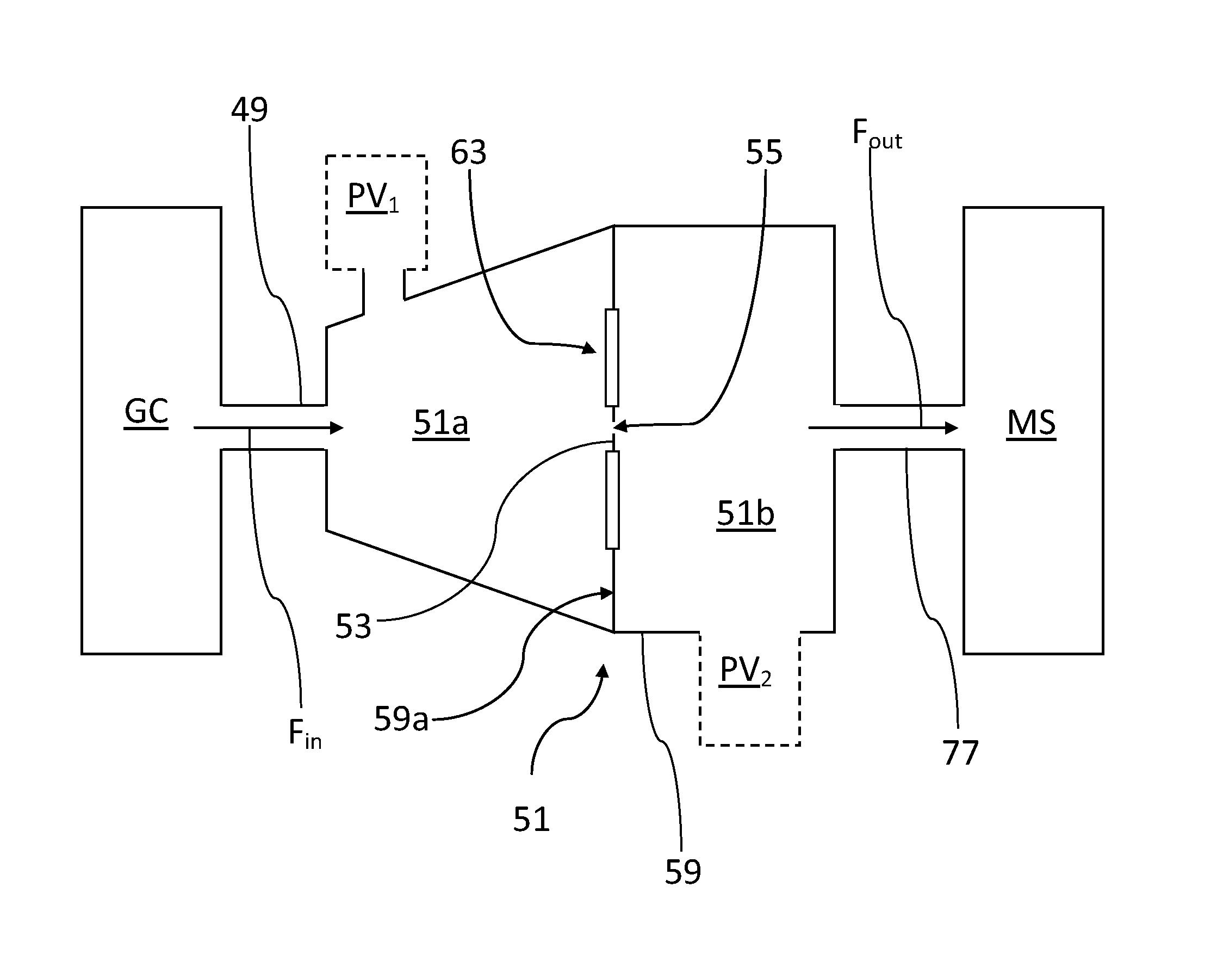
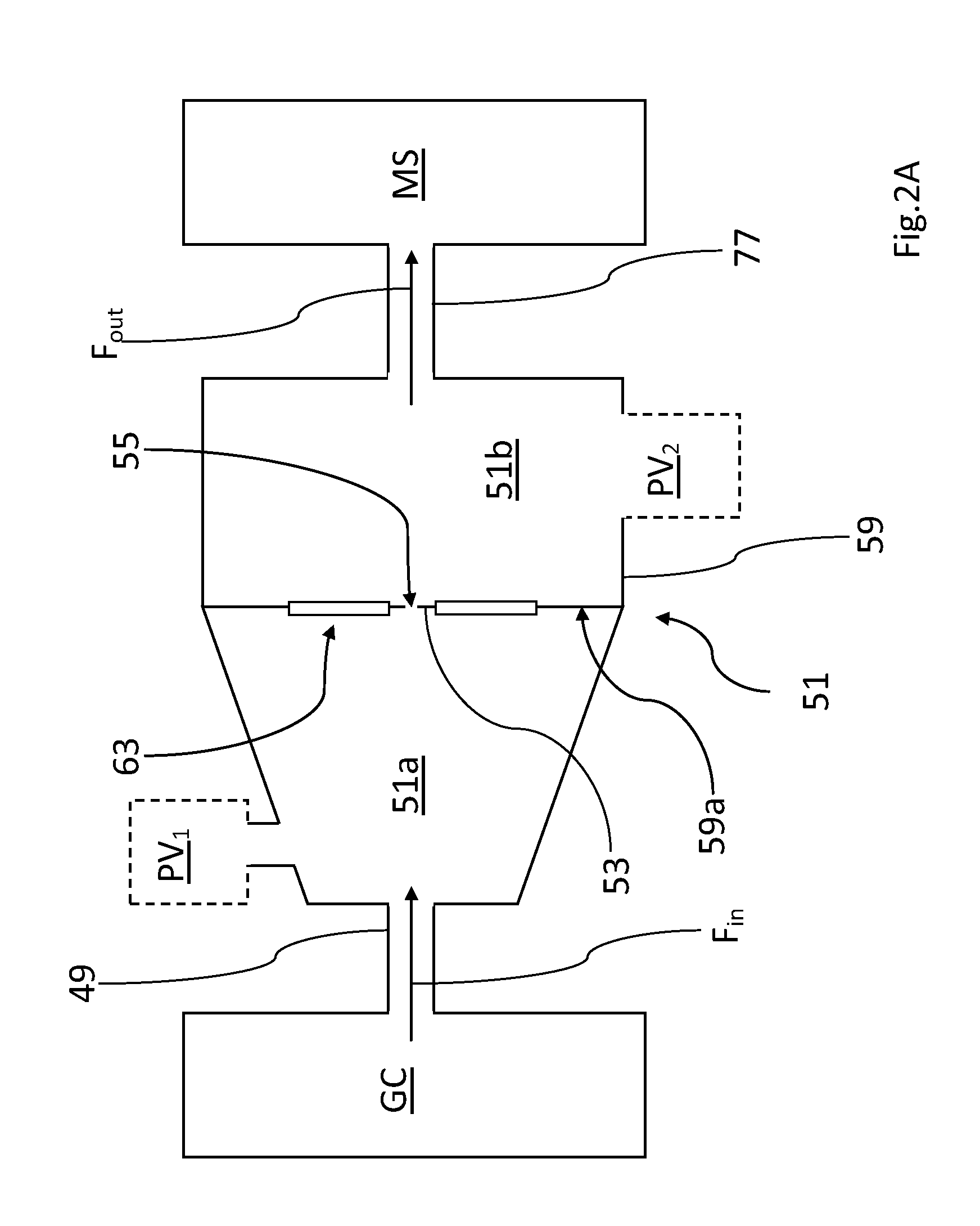
[0036]With reference to FIG. 2A, the GC-MS apparatus according to a first embodiment of the invention comprises a gas chromatographic section GC and a spectrometric analysis section MS. Advantageously, according to the invention, these two sections are respectively associated through an interface section, which is overall denoted by the reference 51 and which is located downstream of the section GC and upstream of the section MS, taking as a reference the preferred path direction followed by the analyte into the apparatus and indicated in the FIG. 2A with the arrows Fin and Fout.

[0037]According to the present invention, the interface section 51 comprises at least a membrane 53 having at least one orifice 55 capable of establishing a molecular flow condition in the analyte passing from the section GC to the section MS through the orifice 55, when the membrane 53 is subjected to a pressure differential such that the pressure pa in the region 51a located upstream of the membrane 53 is ...


PUM


Abstract

GC-MS analysis apparatus has an interface section between GC and MS sections, which is located with respect to the direction of an analyte flow downstream of the GC section and upstream of the MS section. The interface section comprises at least one membrane with at least one orifice capable of establishing a molecular flow condition in the analyte passing between the GC and MS sections through the membrane. The membrane is subjected to a pressure differential such that the pressure pa in a region located upstream of the membrane is higher than the pressure pb in a region located downstream of the membrane.

Description

CROSS REFERENCE TO RELATED APPLICATIONS[0001]This patent application claims the benefit of the Italian priority patent application no. TO2009A000513 filed on Jul. 8, 2009, and also claims further priority to the subsequently filed Italian patent application no. TO2010A000399 filed on May 13, 2010. This patent application relates to the U.S. patent application filed on Jul. 7, 2010, which is presently identified and is titled “GAS SAMPLING DEVICE AND GAS ANALYZER EMPLOYING THE SAME”.TECHNICAL FIELD[0002]The present invention relates to a GC-MS apparatus, the apparatus for the analysis of volatile substances, or substances that can be made volatile, which is based on the combination of gas chromatography (GC) technique and mass spectrometry (MS).BACKGROUND OF THE INVENTION[0003]Gas chromatography is often used in order to separate mixtures of substances, which can be subsequently analysed by means of mass spectrometry technique. As an example, according to the prior art, a GC-MS analy...

Claims


Application Information

Patent Timeline
Patent Type & Authority Patents(United States)
IPC IPC(8): B01D59/44
CPCG01N1/2202H01J49/0422G01N30/722
Inventor CORREALE, RAFFAELE
Owner AGILENT TECH INC
Why Eureka
Try Eureka