Fluid path connectors and container spikes for fluid delivery

a technology of fluid path connector and container spike, which is applied in the direction of branching pipes, special dispensing means, packaged goods, etc., can solve the problems of difficulty in maintaining sterility, difficulty in use, and many fluid path connectors used in medical procedures that exhibit a number of substantial, so as to facilitate rotation (including twisting

Active Publication Date: 2012-10-09
BAYER HEALTHCARE LLC
View PDF19 Cites 46 Cited by
  • Summary
  • Abstract
  • Description
  • Claims
  • Application Information

AI Technical Summary

Problems solved by technology

However, many fluid path connectors used in medical procedures exhibit a number of substantial drawbacks including, for example, difficulty of use and difficulty in maintaining sterility.
Moreover, when such connectors are used at high pressures, leakage and failure also become substantial problems.
In addition to problems associated with, for example, difficulty of use and difficulty in maintaining sterility, it is often difficult to provided a suitable flow rate for certain medical procedures (for example, delivery of a relatively viscous fluid such as a contrast medium) from spike connectors.
The spike of such fluid connectors is typically of limited cross-sectional area to facilitate piercing, resulting in significant limits upon the size of the fluid line or channel passing through the spike.
For example, even the largest fluid line in currently available spike fluid connectors have a cross-sectional area of approximately 0.08 in2, significantly limiting the flow rate of fluids therethrough.

Method used


Image

  • Fluid path connectors and container spikes for fluid delivery
  • Fluid path connectors and container spikes for fluid delivery
  • Fluid path connectors and container spikes for fluid delivery

Examples


Embodiment Construction

[0076]As used herein and in the appended claims, the singular forms “a,”“an”, and “the” include plural references unless the content clearly dictates otherwise. Thus, for example, reference to “a filter” includes a plurality of such filters and equivalents thereof known to those skilled in the art, and so forth, and reference to “the filter” is a reference to one or more such filters and equivalents thereof known to those skilled in the art, and so forth.

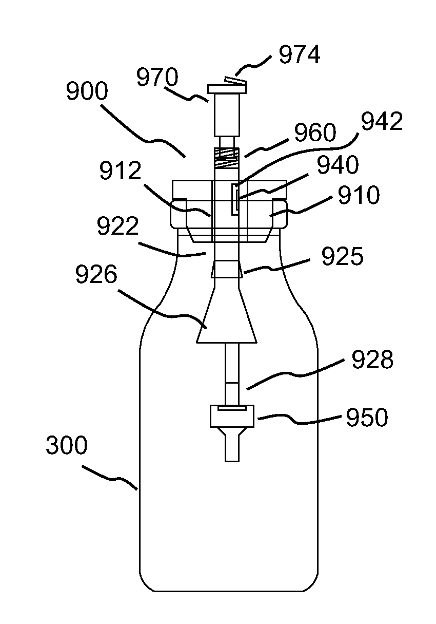
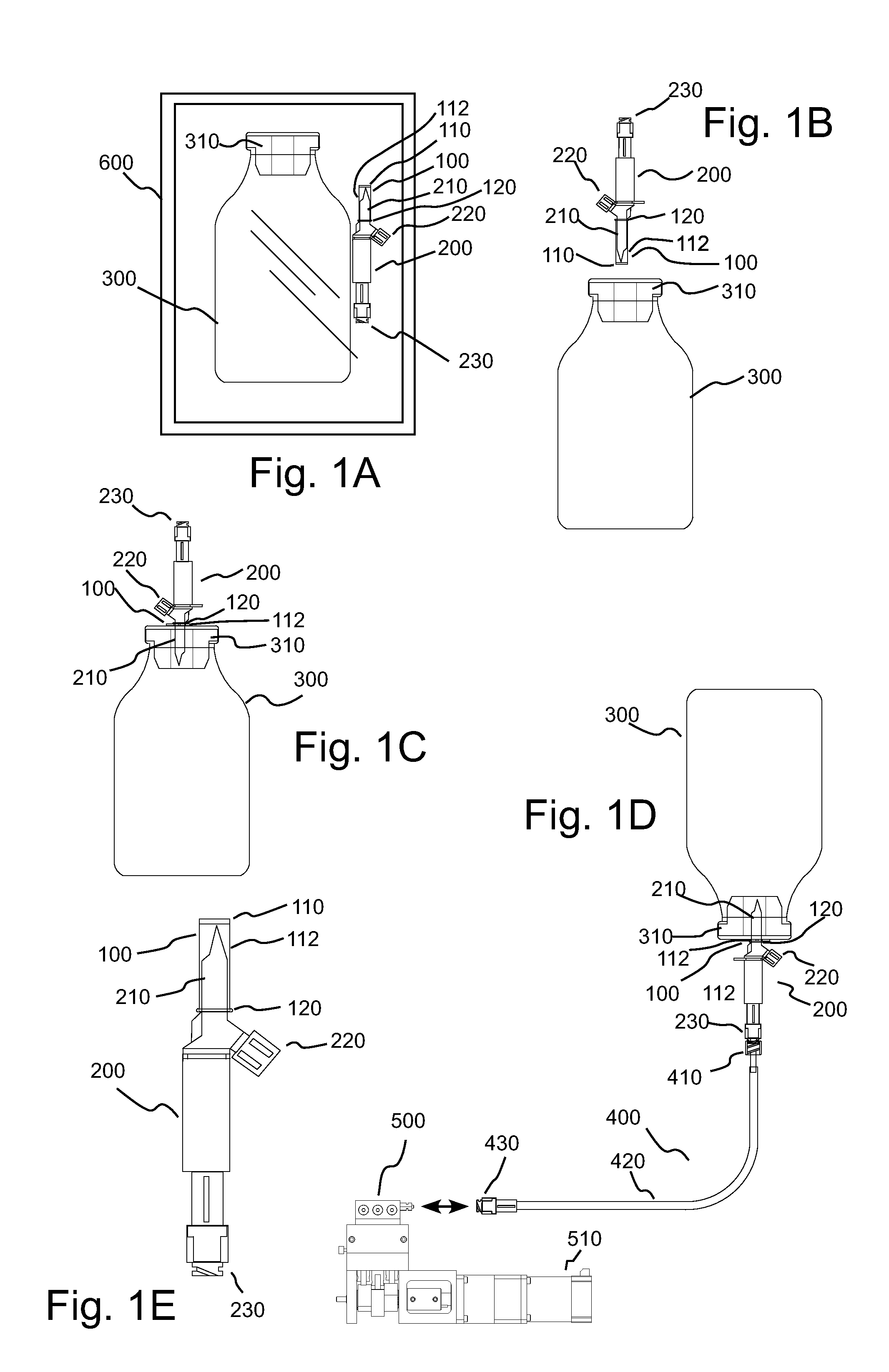
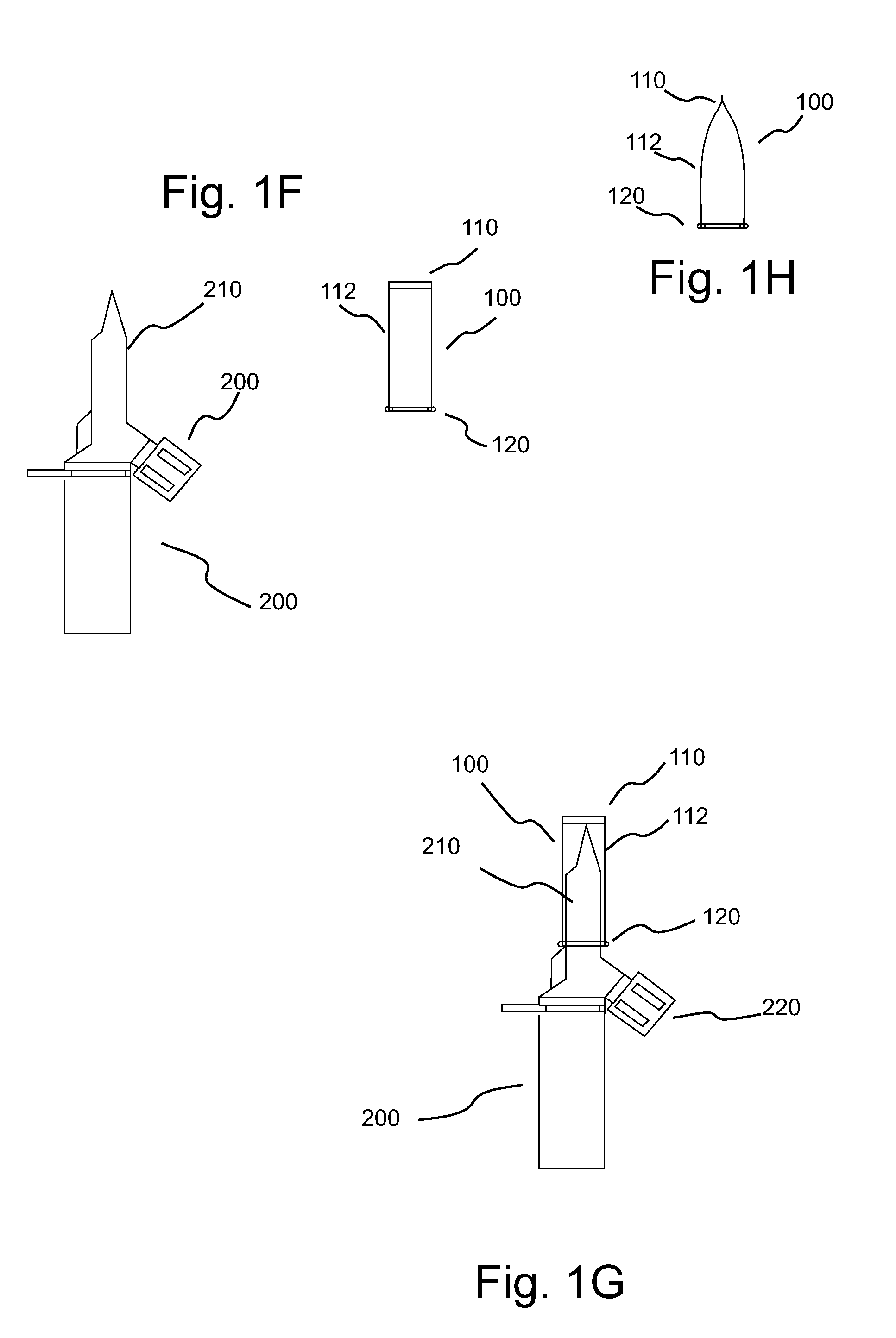
[0077]FIGS. 1A through 1H illustrate an embodiment of a sterility cover, protector or shield 100 for use in connection with a fluid connector 200 (or spike connector). Fluid connector 200 includes a piercing spike 210 to pierce a septum or elastomeric stopper 310 of a fluid container or bottle 300 to place a fluid line or channel passing through spike 210 of fluid connector in fluid connection with container 200. Fluid connector 200 also includes a check ball and air filter 220 in fluid connection with an air line or vent line passi...


PUM


Abstract

A fluid connector system features a stopper and an extending section. Installable within an outlet of a fluid container, the stopper defines a passage therethrough. Defining air and fluid conduits, the extending section has a first abutment member threadably connectible thereto and a second abutment member affixed thereto. The extending section is adapted to be extended through the passage of the stopper when assembled thereto. When the first abutment member is tightened about the extending section, the first and second abutment members abut against the exterior and interior sides, respectively, of the stopper. With the stopper installed within the outlet and the extending section and the abutment members therewith assembled to the stopper thereby sealing the passage therein, fluid within the container may be extracted via the fluid conduit as air exterior to the container flows therein via the air conduct to displace the fluid being extracted from the container.

Description

BACKGROUND OF THE INVENTION[0001]The present invention relates to fluid path connectors and container spikes for fluid delivery and, particularly, to fluid path connectors and container spikes for delivery of sterile, medical fluids.[0002]The following information is provided to assist the reader to understand the invention disclosed below and the environment in which it will typically be used. The terms used herein and objectives described herein are not intended to be limited to any particular narrow interpretation unless clearly stated otherwise in this document. References set forth herein may facilitate understanding of the present invention or the background of the present invention. The disclosure of all references cited herein are incorporated by reference.[0003]In many medical procedures, such as diagnostic and / or therapeutic drug delivery, it is desirable to inject a fluid into a patient. For example, numerous types of contrast media (often referred to simply as contrast) ...

Claims


Application Information

Patent Timeline
Patent Type & Authority Patents(United States)
IPC IPC(8): F16L35/00F16L55/07
CPCA61M5/162A61M5/007A61J1/1406A61M2005/1623Y10T137/8122Y10T137/7856Y10T137/3115Y10T137/86348B33Y70/00B33Y80/00A61M39/24
Inventor TROMBLEY, III, FREDERICK W.REILLY, DAVID M.
Owner BAYER HEALTHCARE LLC
Why Eureka
Try Eureka