Unlock instant, AI-driven research and patent intelligence for your innovation.

Signal processing device

Active Publication Date: 2012-10-09
PANASONIC CORP
View PDF4 Cites 6 Cited by
  • Summary
  • Abstract
  • Description
  • Claims
  • Application Information

AI Technical Summary

Benefits of technology

[0026]According to this structure, an amount of processing required by the second filter unit can be made smaller than an amount of processing required by the first filter unit, and also spaciousness provided by the second filter unit can be made less than spaciousness provided by the first filter unit. As a result, when generating signals of 2 channels from a monaural signal, sharpness of a time variation of a sound and precise localization of a sound image can be realized, while producing favorable stereo signals with a sense of spaciousness in a low frequency band.
[0028]According to this structure, when generating signals of 2 channels from a monaural signal, high frequency band signal processing is simplified. Therefore, sharpness of a time variation of a sound and precise localization of a sound image can be realized and also an amount of computation can be reduced, while producing favorable stereo signals with a sense of spaciousness.
[0030]According to this structure, when generating signals of 2 channels from a monaural signal, sharpness of a time variation of a sound and precise localization of a sound image can be realized and also an amount of computation can be reduced, while producing favorable stereo signals with a sense of spaciousness.
[0042]As is clear from the above description, when generating signals of 2 channels from a monaural signal, the signal processing device according to the present invention can realize sharpness of a time variation of a sound and precise localization of a sound image, provide a sense of spaciousness in a low frequency band, and produce favorable stereo signals.
[0044]Therefore, the present invention has a very high practical value, as distribution of music content to mobile phones and portable information terminals and viewing of such music content have become widespread today.

Problems solved by technology

However, the above method has the following problems.
In a case where the input signal has an extremely sharp time variation (such as an instant at which a metal percussion instrument is struck), due to the effect of the delay and reverberation addition in the decorrelation process, the decorrelated signal loses the sharpness of the input signal.
Since this decorrelated signal and input signal S are added in the mixing process that follows the decorrelation process, the resulting output signals will end up losing the sharpness of the input signal.
Likewise, in a case where frequency components of the input signal unevenly concentrate in a specific frequency band (such as when a timbre of one type of instrument continues), although a sound image of highly precise localization must be created, the effect of the delay and reverberation addition in the decorrelation process causes the sound image of precise localization to be blurred in the decorrelated signal.
This requires an extremely large amount of computation.
This requires a significantly large amount of computation, too.

Method used


Image

  • Signal processing device
  • Signal processing device
  • Signal processing device

Examples


first embodiment

[0068]The following describes a signal processing device according to the present invention, with reference to drawings.

[0069](First Embodiment)

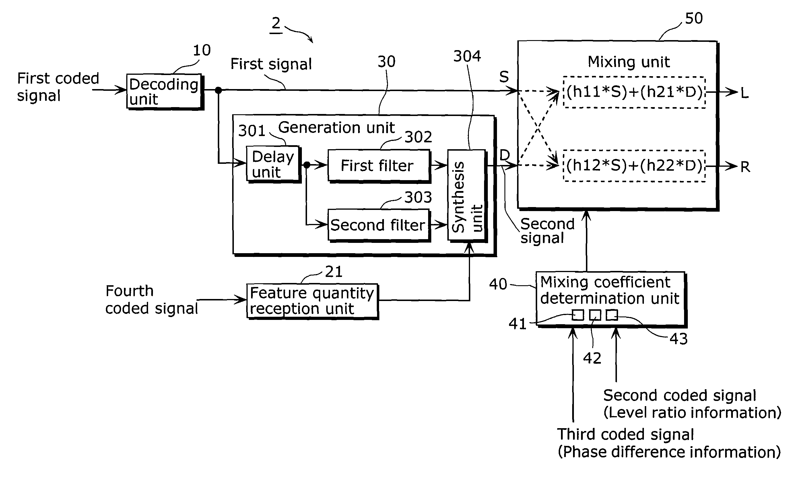
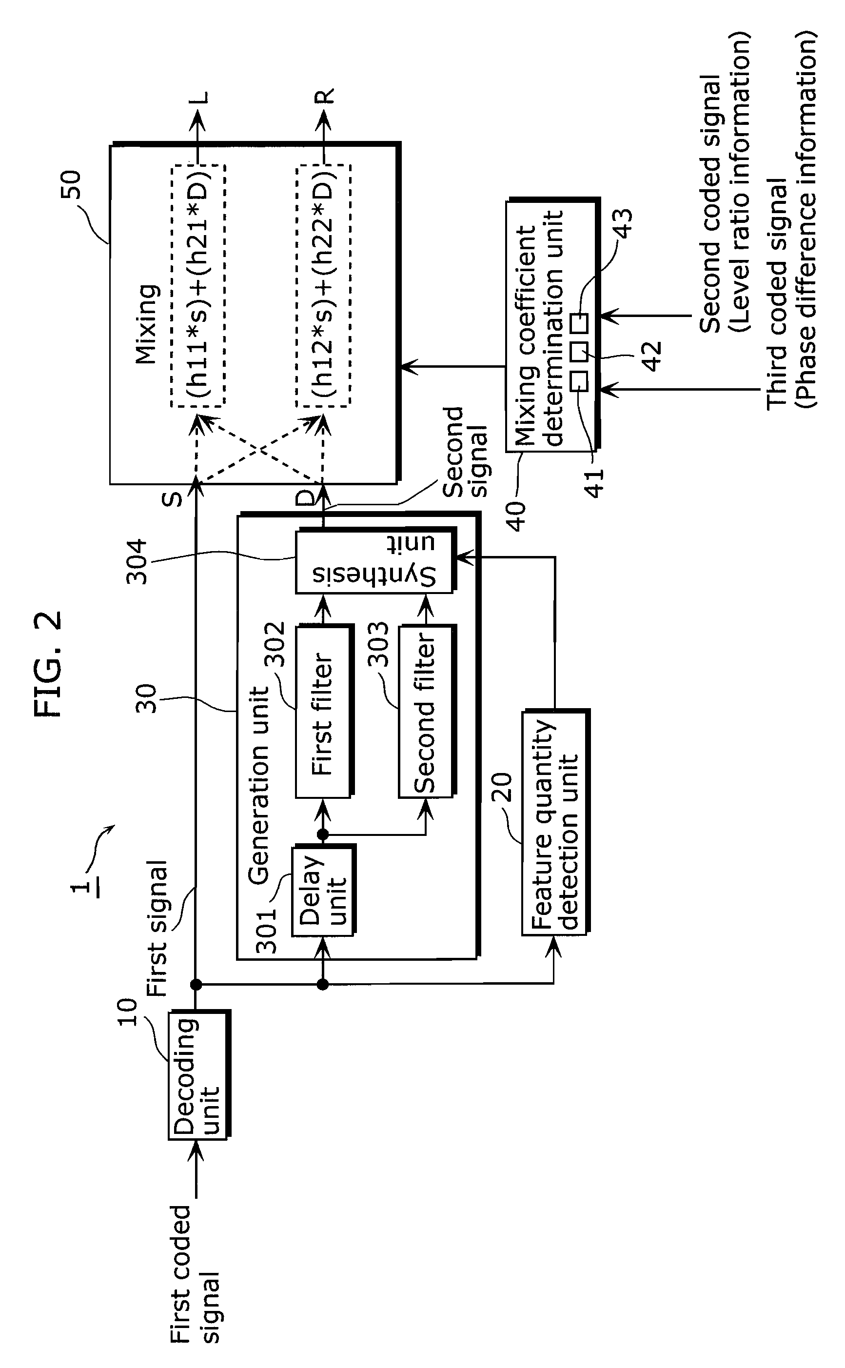
[0070]FIG. 2 is a functional block diagram showing a structure of the signal processing device according to the first embodiment. It should be noted that a decoding unit 10 is shown in the drawing too.

[0071]A signal processing device 1 is a device for decoding a bit stream that includes: a first coded signal generated by coding a downmixed signal of two audio signals; a second coded signal which is level ratio information generated by coding a value determined in accordance with level ratio L between the two audio signals; and a third coded signal which is phase difference information generated by coding a value determined in accordance with phase difference θ between the two audio signals. As shown in FIG. 2, the signal processing device 1 includes a feature quantity detection unit 20, a generation unit 30, a mixing coefficient determinatio...

second embodiment

[0130](Second Embodiment)

[0131]The following describes a signal processing device 3 according to the second embodiment of the present invention, with reference to drawings.

[0132]A main difference of the second embodiment from the first embodiment lies in the following. In the first embodiment, a method of generating a second signal is adapted in accordance with each signal that is inputted successively. In the second embodiment, on the other hand, considering that a low frequency band signal greatly contributes to sound reverberation and spaciousness whereas a high frequency band signal does not much contribute to sound reverberation and spaciousness, a generation unit is changed between a low frequency band and a high frequency band in order to reduce an amount of computation.

[0133]FIG. 8 shows a structure of the signal processing device according to the second embodiment of the present invention. Note here that structural parts corresponding to those of the signal processing devic...


PUM


Abstract

A signal processing device includes a generation unit that generates a second signal from a first signal that is obtained by down mixing two signals; a mixing coefficient determination unit that determines, based on a value L and a value θ, a mixing degree for mixing the first signal and the second signal; and a mixing unit that mixes the first signal and the second signal based on the mixing degree determined by the mixing coefficient determination unit. The generation unit includes a first filter that generates a low frequency band signal in the second signal, from a low frequency band signal in the first signal; and a second filter that generates a high frequency band signal in the second signal, from a high frequency band signal in the first signal. The first filter is a filter unit which, for a complex-number signal, de-correlates an input signal and adds a reverberation component by using a delay unit and an all pass filter, and the processing unit is a filter unit different from the first filter.

Description

BACKGROUND OF THE INVENTION[0001]1. Technical Field[0002]The present invention relates to signal processing devices for decoding a coded signal that is generated by coding a downmixed signal of a plurality of signals and information for dividing the downmixed signal into the original signals. The present invention particularly relates to techniques of decoding a coded signal that is generated by coding a phase difference and a level ratio between signals to realize coding of multichannel realism with a small amount of information.[0003]2. Background Art[0004]A technique called a spatial codec (spatial coding) has been developed in recent years. This technique aims for compression coding of multichannel realism with a very small amount of information. For example, while AAC, which is a multichannel codec already widely used as a digital television audio format, requires a bit rate of 512 kbps or 384 kbps for 5.1 channels, the spatial codec is intended for compression coding of multic...

Claims


Application Information

Patent Timeline
IPC IPC(8): H04B1/00G10L19/02G10L19/00
CPCH04S3/002G10L19/008H04S2420/03
Inventor MIYASAKA, SHUJITAKAGI, YOSIAKINORIMATSU, TAKESHIKAWAMURA, AKIHISAONO, KOJIRO
Owner PANASONIC CORP