Wrapping tape for a cable harness

a cable harness and wrapping tape technology, applied in the field of wrapping tape, can solve the problems of only being able to use machines only to a limited extent, unable to achieve the effect of avoiding unintentional connections, low error rate, and cost-effectiveness

Inactive Publication Date: 2012-12-18
NEWFREY
View PDF31 Cites 6 Cited by
  • Summary
  • Abstract
  • Description
  • Claims
  • Application Information

AI Technical Summary

Benefits of technology

[0011]One object of the present invention is therefore to provide a system and method with which cables, cable looms and cable harnesses are bound in an automated manner and can be arranged in a desired circumferential position by a fastening element. A particular aim is to avoid unintentional connections between the wrapping tape and the article to be wrapped. Furthermore, air gaps between the articles to be wrapped are to be kept as small as possible. In this case, particular value is placed on process reliability and a low error rate. The system should be so cost-effective that it can be implemented in industrial countries. The fastening elements should be fixed in the correct location, in terms of the cable harness circumference, as early as during production of the cable harness.

Problems solved by technology

A harness of this type has only a limited degree of flexibility and can then be installed.
These movement sequences are obviously difficult to automate.
To date, it has been possible to use machines only to a limited extent.
However, corresponding actions can also be learnt quickly with little occupational skill.
However, a manual production process has the disadvantages of a higher expected error rate and greater outlay on quality assurance.
The additional problem of how to fix cable harnesses in the motor vehicle arises here.
However, these fastening elements have to be manually fitted to the cable harness.
However, these devices have the disadvantage that they are too heavy and too bulky.
The wires of the harness may be unintentionally welded together during the welding process.
Furthermore, the L-shaped mating pieces leave behind an air gap after being withdrawn from the cable bundle after a welding process has taken place, so that the previously tightened wires may, under certain circumstances, become slack again.

Method used


Image

  • Wrapping tape for a cable harness
  • Wrapping tape for a cable harness
  • Wrapping tape for a cable harness

Examples


Embodiment Construction

[0088]In the description of the invention which follows, identical features are provided with similar reference symbols. Where identical reference symbols are used, the features are unchanged. Deviations and modifications will be explicitly explained.

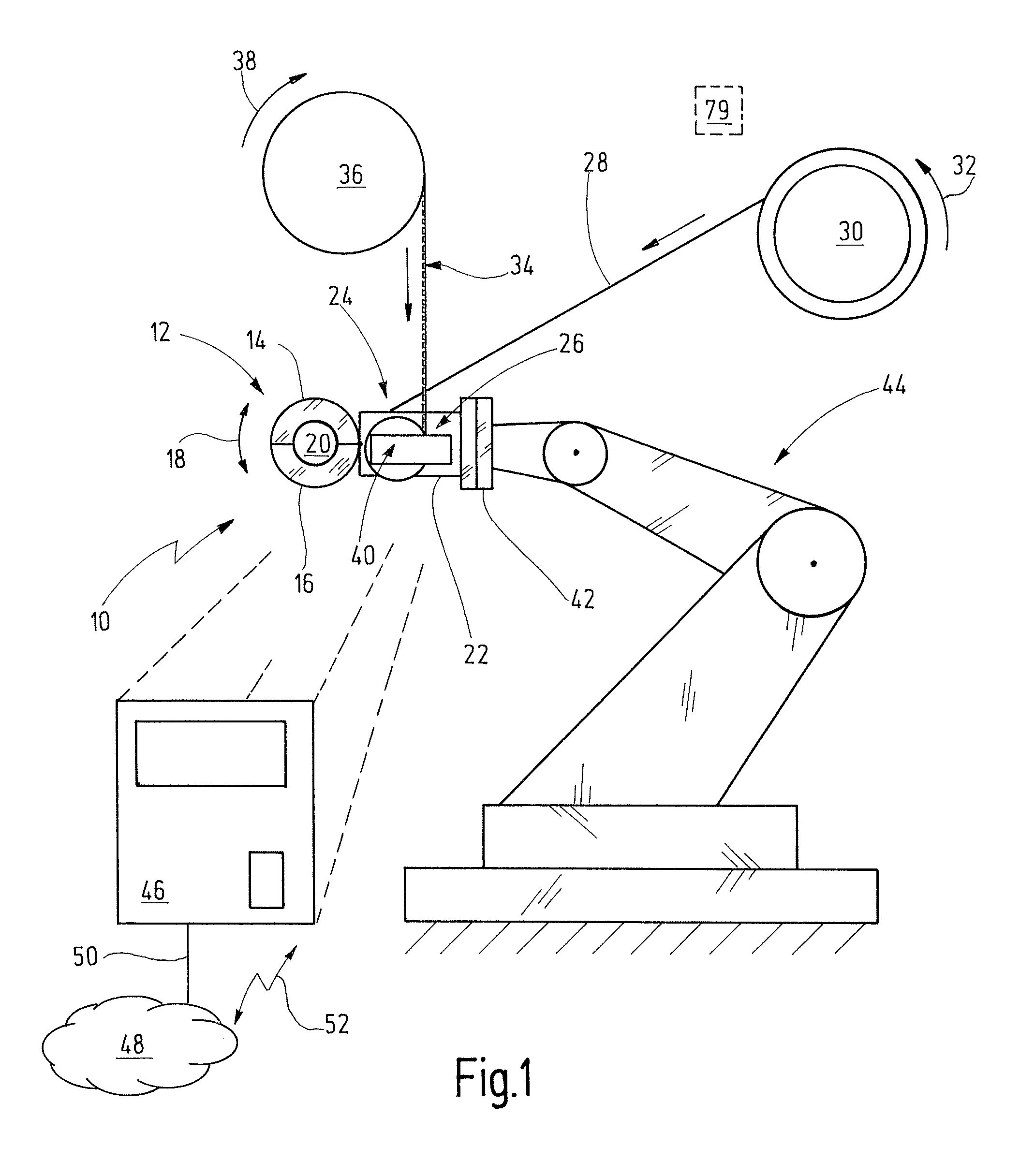
[0089]FIG. 1 shows an apparatus 10 according to the present invention which is fitted to a multiple-axis robot.

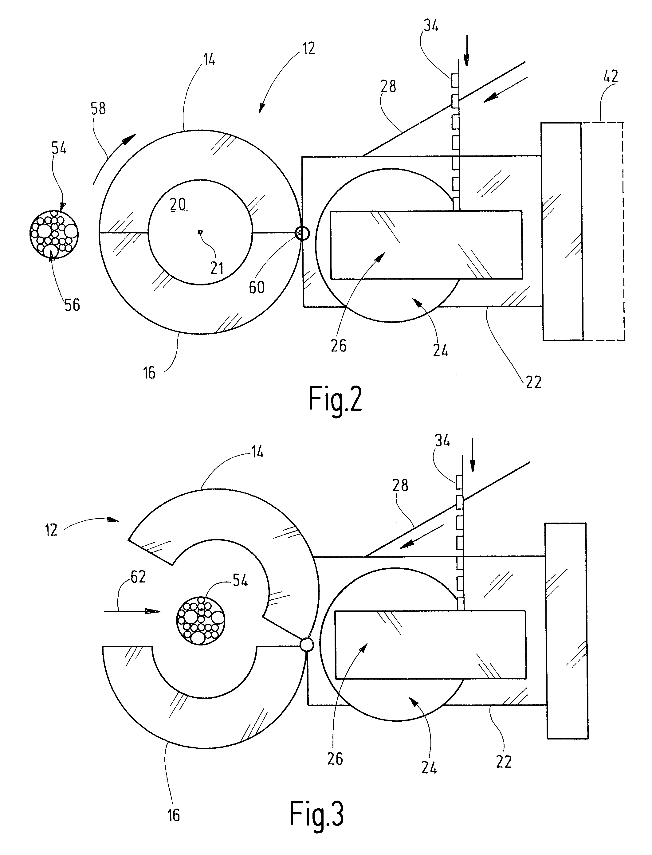
[0090]The apparatus 10 has a gripper device 12 which, in turn, comprises a first jaw or a pincer 14 and a second jaw respectively a pincer 16. The first jaw 14 and the second jaw 16 are illustrated in a closed position in FIG. 1. The jaws 14, 16 are mounted such that they can move relative to one another. In the specific example of FIG. 1, the jaws 14, 16 are mounted such that they can pivot in relation to one another, with the first jaw 14 being pivotable and the second jaw 16 being fixed. It goes without saying that both jaws 14, 16 could be movable and that the jaws 14, 16 are, as an alternative, also mounted such that they ...


PUM

PropertyMeasurementUnit
frequenciesaaaaaaaaaa
timeaaaaaaaaaa

Abstract

A wrapping tape for automatically circumferentially wrapping an axially extending article, in particular a cable or a cable loom, the tape suitable for wrapping around the article and then tautened and joined to itself in an overlapping manner by a joining tool. The wrapping tape comprises a core with a contact area, which is designed to rest on the article; and tabs protruding laterally from the core. A tab forms such an angle with the contact area that the joining tool can engage behind the tab when the tape is wrapped tightly around the article, and without the tool engaging behind the contact area, while tabs of overlapping tape portions are joined to one another.

Description

CROSS-REFERENCE TO RELATED APPLICATIONS[0001]This application is a continuation of PCT Application No. PCT / US2009 / 041968, filed Apr. 28, 2009 which claims the benefit of German Patent Application No. 102008022336.0, filed Apr. 29, 2008.BACKGROUND OF THE INVENTION[0002]The present invention relates to an apparatus and a method for automatically, circumferentially wrapping articles which extend in the axial direction, in particular cables or cable looms, as used, for example, in the automotive industry as a cable harness. The invention particularly relates to a wrapping tape and a fastening element, which are used for automatic, circumferential wrapping purposes.[0003]Cable harnesses are frequently used in automobile construction. A cable harness is a loom of cables which transmit signals or information or operating currents (energy). The cables are combined, for example, by clips, cable binders or tubes. Modern motor vehicles may have electrical wires which, in total, can reach a dis...

Claims


Application Information

Patent Timeline
Patent Type & Authority Patents(United States)
IPC IPC(8): B32B3/00B32B3/30B32B3/28
CPCH01B13/085Y10T428/24479Y10T428/24628Y10T428/2457Y10T428/195Y10T428/24777Y10T428/24595
Inventor SCHAETY, HARALDSTIGLER, MARIOSENG, HANS-PETERGERLACH, WOLFGANG
Owner NEWFREY
Why Eureka
Try Eureka