Designing drilling pattern for excavating rock cavern

a drilling pattern and rock cavern technology, applied in the direction of process and machine control, instruments, computer control, etc., can solve the problems of cumbersome and slow use, difficult to change the finished drilling pattern later, etc., to achieve easy and fast editing improve the control of the properties of the drilling pattern, and improve the effect of design and construction speed

Inactive Publication Date: 2013-03-05
SANDVIK MINING & CONSTR OY
View PDF9 Cites 11 Cited by
  • Summary
  • Abstract
  • Description
  • Claims
  • Application Information

AI Technical Summary

Benefits of technology

[0011]An advantage of the invention is that it is easier and faster to design a drilling pattern than before. The designer can concentrate on determining the location and properties of the master holes because the drilling pattern design program can automatically determine properties of holes dependent on the master holes. Further, the properties of the drilling pattern can be controlled better. Further, the dominating properties and the location of the editable master holes can be changed afterwards. Owing to this, it is easy and fast to edit the drilling pattern later. The designer may also use an old drilling pattern as the basis of a new pattern and to modify master holes in it in the way required by the new round to be drilled, which results in savings in the design work. Owing to good editability, the drilling pattern may have a long service life.
[0012]The idea of an embodiment is to determine at least two master holes for a group of holes in the drilling pattern. Between the master holes, there are one or more intermediate holes, at least one property of which is determined on the basis of the dominating properties of the master hole. In this solution, by means of the master holes it is possible to easily mark off the area of influence comprising one or more intermediate holes influenced by the master holes. The size of the area of influence may be edited afterwards by changing the location of the master holes.
[0013]The idea of an embodiment is to determine for each individual master hole an area of influence comprising one or more drill holes. The area of influence may be determined when the drilling pattern is designed, and it may be edited afterwards. The area of influence may be determined in such a way, for example, that it comprises a predetermined number of drill holes closest to the master hole, or drill holes at a predetermined absolute distance from the master hole. Further, the area of influence may be determined in such a way that the master hole has influence only in a given part of the pattern, for example in the bottom section or in the corner. Further, the area of influence may comprise drill holes positioned between the master hole and some part of the pattern, such as a corner point. The rule determining the area of influence of the master hole may be stored in the same editable data element as the dominating properties of the master hole. This application even allows positioning in desired sections only one master hole that affects a predetermined number of drill holes.
[0014]The idea of an embodiment is that the dominating property of a master hole is one of the following: location in the group of holes, depth, hole direction angle, degree of charge or hole spacing.
[0015]The idea of an embodiment is to display the drilling pattern to be designed in a graphic user interface and to move the master hole along the group of holes of the pattern to a desired location. The moving may take place for instance with a mouse in the user interface or a corresponding pointer device. Then, when the master holes are linked to the profile line, they are easy to move along the profile line during editing.
[0016]The idea of an embodiment is to convert any drill hole into a master hole, and vice versa. Thus, new kinds of drill hole elements can be easily formed in the group of holes.

Problems solved by technology

A disadvantage of the present drilling pattern design programs is, however, that they are cumbersome and slow to use.
Further, it is difficult to change finished drilling patterns later.

Method used


Image

  • Designing drilling pattern for excavating rock cavern
  • Designing drilling pattern for excavating rock cavern
  • Designing drilling pattern for excavating rock cavern

Examples


Embodiment Construction

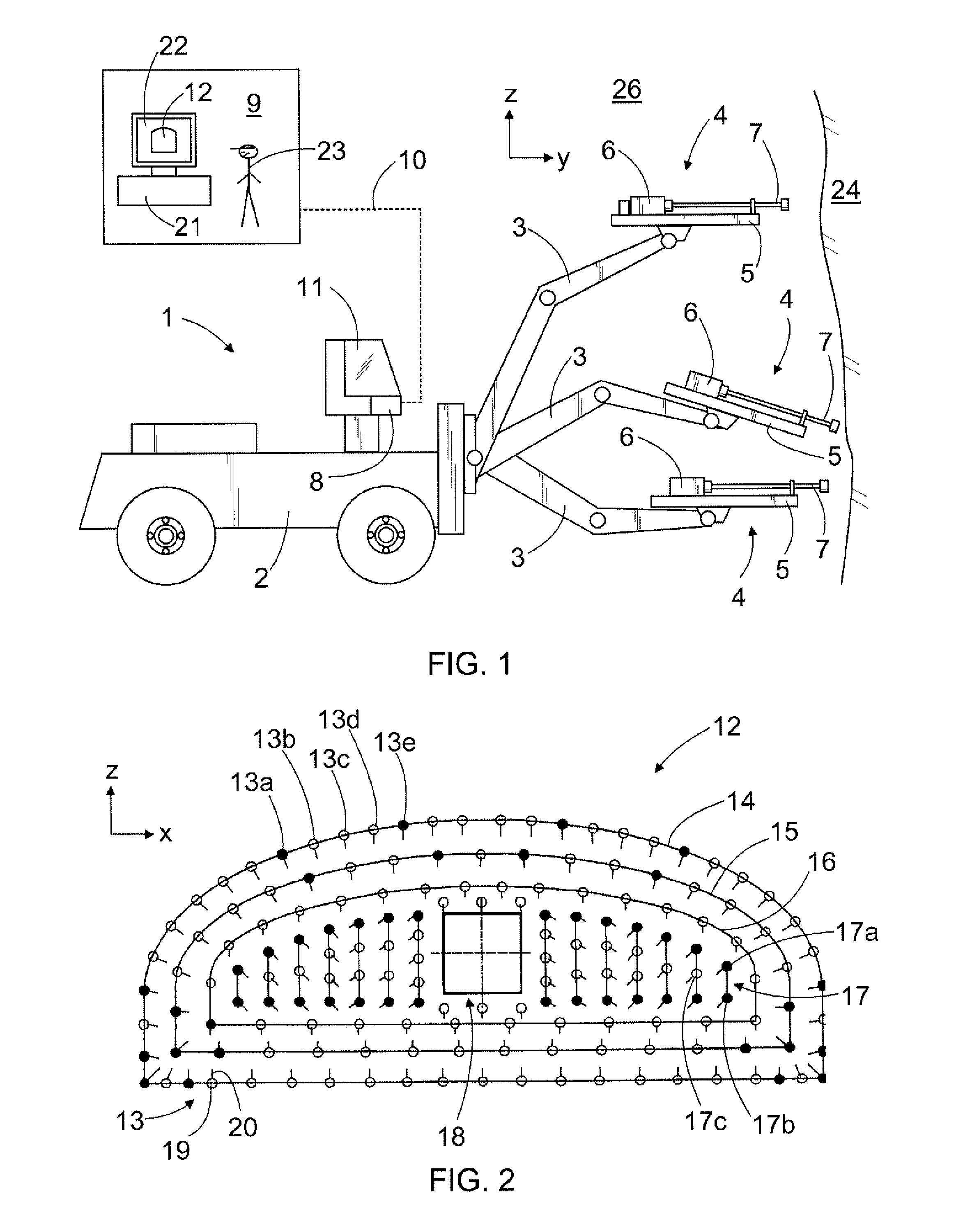
[0048]FIG. 1 shows a rock drilling rig 1 comprising a movable carrier 2, one or more drilling booms 3 and drilling units 4 arranged in the drilling booms 3. The drilling unit 4 comprises a feed beam 5 on which a rock drilling machine 6 can be moved by means of a feed device. Further, the drilling unit 4 comprises a tool 7 with which the impact pulses given by the percussion device of the rock drilling machine are transmitted to the rock to be drilled. The rock drilling rig 1 further comprises at least one control unit 8 arranged to control actuators of the rock drilling rig 1. The control unit 8 may be a computer or a corresponding device, and it may comprise a user interface with a display device as well as control means for giving commands and information to the control unit 8.

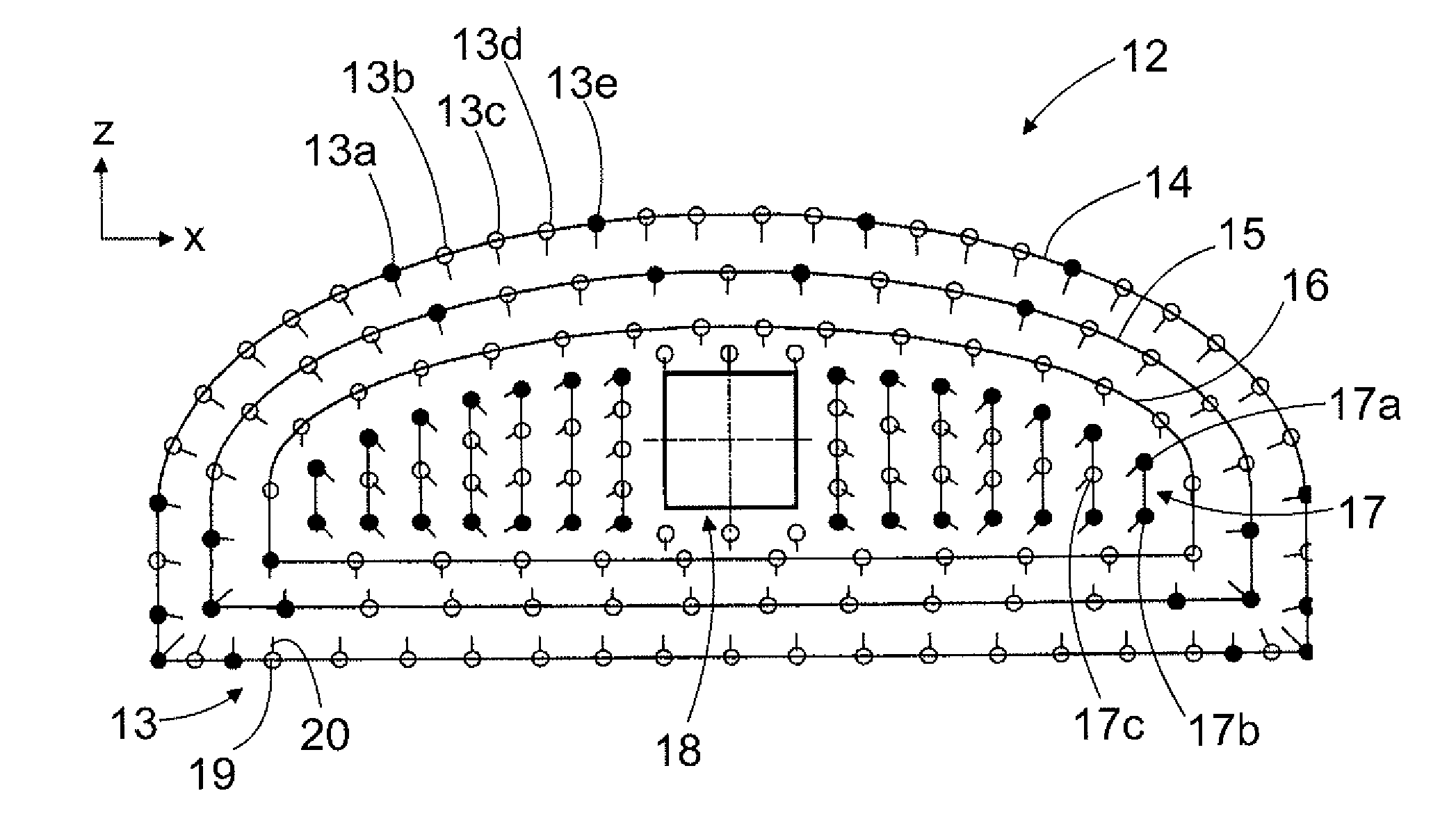
[0049]Typically, for drilling each round a drilling pattern 12 is designed in which at least the locations and the hole direction angles of the holes to be drilled in the coordinate system of the drilling pa...


PUM


Abstract

A method and a storage device including a software product for designing a drilling pattern, and further a rock drilling rig, in the control unit of which a software product may be executed for designing the drilling pattern. For a group of holes of the drilling pattern, at least one master hole can be determined which comprises at least one dominating factor. The properties of at least one other drill hole are determined on the basis of the dominating properties of the master hole. A master hole may be a hole location master, hole depth master or hole direction master.

Description

CROSS REFERENCE TO RELATED APPLICATIONS[0001]This application is the National Stage of International Application No. PCT / FI2007 / 050710, filed Dec. 19, 2007, and claims benefit of Finnish Application No. 20065854, filed Dec. 22, 2006.BACKGROUND OF THE INVENTION[0002]The invention relates to designing a drilling pattern for excavating a rock cavern. The drilling pattern defines for a round to be drilled in the tunnel face at least the locations and hole direction angles of the drill holes in the coordinate system of the drilling pattern. In the method, a designer designs a drilling pattern with the assistance of a drilling pattern design program. An object of the invention is described in more detail in the preamble of the first independent claim.[0003]The invention also relates to a software product, the execution of which in a design computer generates actions required in designing a drilling pattern. Further, the invention relates to a rock drilling rig, in the control unit of whic...

Claims


Application Information

Patent Timeline
Patent Type & Authority Patents(United States)
IPC IPC(8): G06F19/00E21B44/00
CPCE21D9/006F42D1/08G06F17/50E21B44/00F42D3/04G06F30/00
Inventor SALENIEMI, TOMMIEILO, ERKKIJUNNIKKALA, ARIKOSKELAINEN, JUSSIMUONA, JOUKOKESKINEN, MARTTI
Owner SANDVIK MINING & CONSTR OY
Why Eureka
Try Eureka