Supercharge Your Innovation With Domain-Expert AI Agents!

Cable assembly for a connector system

a connector system and cable technology, applied in the direction of electrical equipment, printed circuits, selection arrangements, etc., can solve the problems of increasing signal loss, length of traces, and inherent signal loss in a trace through the midplane circuit board

Active Publication Date: 2013-03-19
TE CONNECTIVITY CORP
View PDF7 Cites 18 Cited by
  • Summary
  • Abstract
  • Description
  • Claims
  • Application Information

AI Technical Summary

Benefits of technology

The solution provides a cost-effective, reliable midplane connector system capable of supporting high-speed signals with reduced signal loss and improved heat dissipation, maintaining electrical performance and reducing component temperatures.

Problems solved by technology

Some signal loss is inherent in a trace through the midplane circuit board.
The increased number of traces and the length of the traces introduce more and more signal loss, particularly at higher signal speeds.
Alignment of the connectors is problematic.
Holding the connectors on the circuit boards within tight tolerances increases the cost of the connector system.
Typically, different types of electrical connectors are designed for each of the connector systems, which increases the overall cost of the connector system.
The different types electrical connectors for use in the midplane connector system generally degrades high speed signals passed therethrough due to discontinuities and the asymmetric nature of the connector configuration.
Additionally, the complex design of the connectors, particularly with the connectors used in orthogonal midplane applications, increase the overall cost of the connector system.
With high speed connector systems, the temperature of the components used in the connector system are typically higher, and heat dissipation from such components heretofore has proven difficult.

Method used


Image

  • Cable assembly for a connector system
  • Cable assembly for a connector system
  • Cable assembly for a connector system

Examples


Embodiment Construction

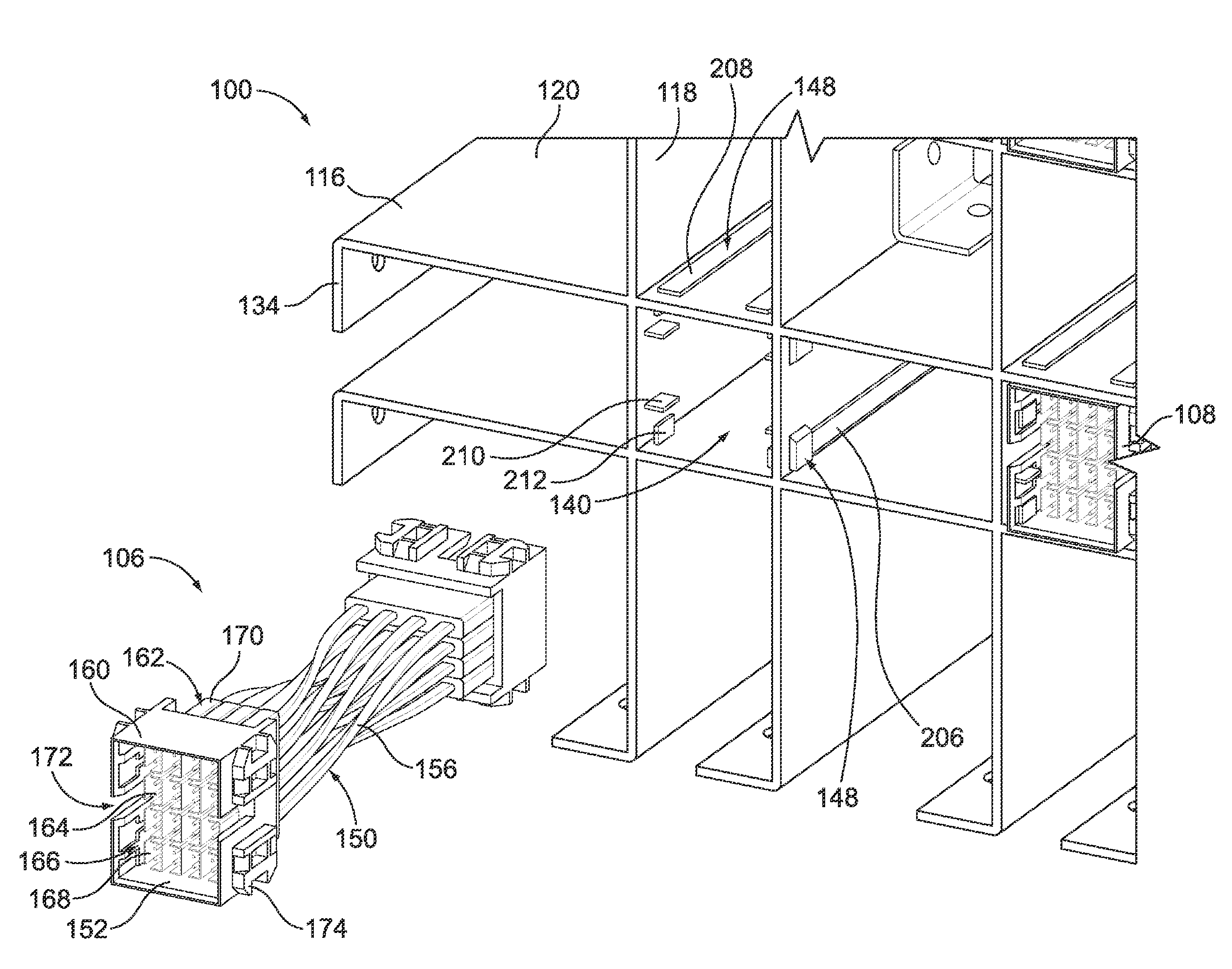
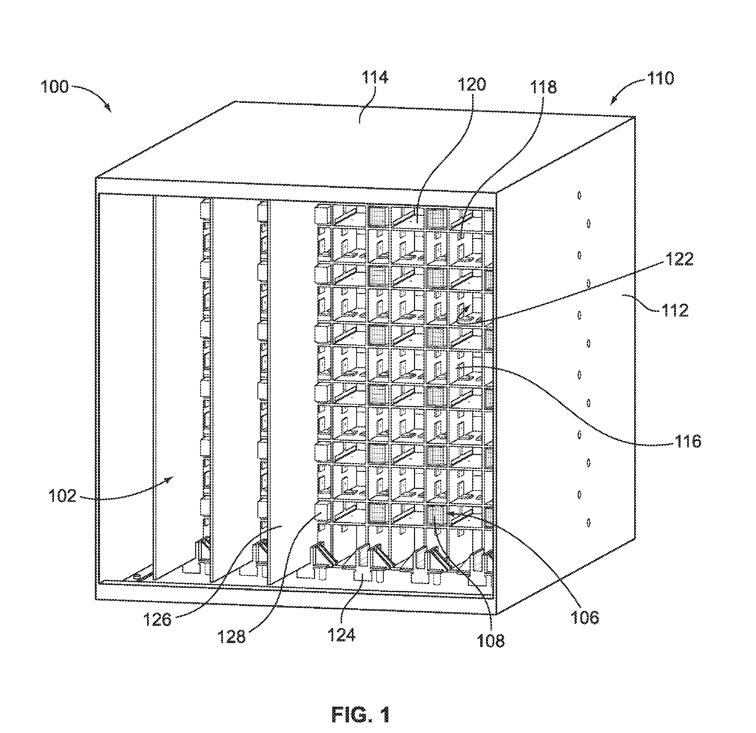
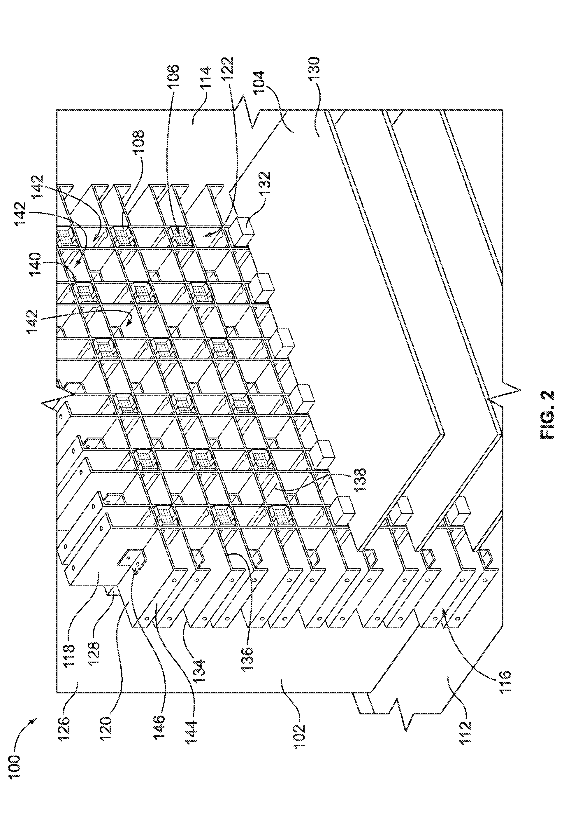
[0027]FIG. 1 is a front perspective view of a connector system 100 formed in accordance with an exemplary embodiment. In an exemplary embodiment, the connector system 100 is utilized to connect a plurality of front cards 102 with a plurality of rear cards 104 (shown in FIG. 2). The front cards 102 may be line cards or server blade cards and the rear cards 104 may be switch cards or I / O cards. Other types of cards may be used in alternative embodiments. The connector system 100 may be arranged in different configurations to hold the front cards 102 and the rear cards 104 at different orientations. For example, in a first configuration, the front cards 102 may be oriented vertically and the rear cards 104 may be oriented horizontally. When the connector system 100 is set up in such a configuration, the connector system 100 defines an orthogonal connector system. In another configuration, the front cards 102 may be held horizontally and the rear cards 104 may also be held horizontally....


PUM


Abstract

A connector system includes a chassis that has a framework of panels that defines a plurality of cells extending between first ends and second ends. A clip is coupled to the framework within a corresponding cell. A cable assembly is received in a corresponding cell. The cable assembly includes a first header connector coupled to the framework at the first end of the corresponding cell using the clip and a second header connector is coupled to the framework at the second end of the corresponding cell using the clip. The first header connector has a housing that holds a plurality of contacts. The housing of the first header connector has a first mating interface. The second header connector has a housing that holds a plurality of contacts. The housing of the second header connector has a second mating interface that faces in an opposite direction from the first mating interface. A cable bundle has a plurality of cables that extends between the first and second header connectors. The cables are connected between corresponding contacts of the first header connector and the contacts of the second header connector.

Description

BACKGROUND OF THE INVENTION[0001]The subject matter herein relates generally to cable assemblies, and more particularly to cable assemblies for connector systems.[0002]Some connector systems, such as network switches or computer servers with switching capability, include large backplanes with several switch cards and line cards plugged into the backplane. Generally, the line cards bring data from external sources into the system. The switch cards contain circuitry that may switch data from one line to another. Traces in the backplane interconnect the line cards and the appropriate switch cards. Other connector systems utilize midplanes to interconnect several switch cards and line cards plugged into the midplane. The midplane includes a printed circuit board to which the switch cards and line cards are connected. The midplane provides connectors on both sides of the circuit board, allowing daughter cards, such as the switch cards and line cards, to be connected on both sides of the ...

Claims


Application Information

Patent Timeline
Patent Type & Authority Patents(United States)
IPC IPC(8): H01R11/00
CPCH04Q1/025H01R11/00H05K7/1445H04Q1/035
Inventor COSTELLO, BRIAN PATRICK
Owner TE CONNECTIVITY CORP
Features
  • R&D
  • Intellectual Property
  • Life Sciences
  • Materials
  • Tech Scout
  • Unparalleled Data Quality
  • Higher Quality Content
  • 60% Fewer Hallucinations
Learn More